@rulecad/frames 0.0.1 → 0.1.8
This diff represents the content of publicly available package versions that have been released to one of the supported registries. The information contained in this diff is provided for informational purposes only and reflects changes between package versions as they appear in their respective public registries.
- package/CHANGELOG.md +23 -0
- package/README.md +1182 -21
- package/beam.d.mts +145 -0
- package/beam.mjs +201 -0
- package/bought.d.mts +60 -0
- package/bought.mjs +195 -0
- package/catalogue.d.mts +20 -0
- package/catalogue.mjs +268 -0
- package/cutlist.d.mts +88 -0
- package/cutlist.mjs +199 -0
- package/cutsheet.d.mts +23 -0
- package/cutsheet.mjs +118 -0
- package/door.d.mts +127 -0
- package/door.mjs +254 -0
- package/ends.d.mts +130 -0
- package/ends.mjs +290 -0
- package/fitting.d.mts +262 -0
- package/fitting.mjs +535 -0
- package/frames.d.mts +18 -9
- package/frames.mjs +43 -10
- package/guide.d.mts +140 -0
- package/guide.mjs +269 -0
- package/jig.d.mts +146 -0
- package/jig.mjs +332 -0
- package/join.d.mts +244 -0
- package/join.mjs +257 -0
- package/ops.d.mts +44 -0
- package/ops.mjs +324 -0
- package/package.json +75 -8
- package/panel.d.mts +225 -0
- package/panel.mjs +374 -0
- package/profile.d.mts +268 -0
- package/profile.mjs +462 -0
- package/rods.d.mts +195 -0
- package/rods.mjs +475 -0
- package/section.d.mts +43 -0
- package/section.mjs +140 -0
- package/services.d.mts +335 -0
- package/services.mjs +486 -0
- package/slotnut.d.mts +210 -0
- package/slotnut.mjs +394 -0
- package/square.d.mts +23 -0
- package/square.mjs +42 -0
- package/wheels.d.mts +141 -0
- package/wheels.mjs +337 -0
package/README.md
CHANGED
|
@@ -4,36 +4,1197 @@ Structures built from beams. A beam is a length of a profile: an aluminium extru
|
|
|
4
4
|
plain tube or angle, or a beam printed in plastic. Part of [rulecad](https://github.com/JoniBach/rulecad), a kit for
|
|
5
5
|
designing physical things where every measurement says which rule it comes from.
|
|
6
6
|
|
|
7
|
-
|
|
8
|
-
|
|
7
|
+
It reads a profile, which is everything the rest is built on, makes beams of it, works them, lists what to buy and
|
|
8
|
+
cut, and fastens to them:
|
|
9
|
+
|
|
10
|
+
- **`profileModel`**: a profile as a model from its rule set and its slot family's, every figure with how far to
|
|
11
|
+
trust it and where it comes from, its slots, bores and hollows each in their place.
|
|
12
|
+
- **`outline`**: its section as closed loops, drawn from a handful of dimensions, or a measured outline where you
|
|
13
|
+
have one.
|
|
14
|
+
- **`section`**: what that outline is worth as a beam (area, centroid, second moments, torsion constant, mass per
|
|
15
|
+
metre), each beside the figure on the maker's sheet.
|
|
16
|
+
- **`profileFindings`**: what a check of a profile finds, as `cad rules check` reports it.
|
|
17
|
+
- **`beamModel`** and **`beam`**: a length of a profile, with its mass and centre of mass, the anchors an assembly
|
|
18
|
+
places it and its fittings by, and its solid as a light box or the true section.
|
|
19
|
+
- **Beams in assemblies**: every place on a beam has an address (`top@120`, `top.2@50%`, `a.1`) that a cad
|
|
20
|
+
assembly places a beam's ends and its fittings by, its face names turning with it.
|
|
21
|
+
- **Operations on a beam**: cut, mitre, tap, access, drill, counterbore, pocket, notch and deburr, each placed by an
|
|
22
|
+
address on the beam, dimensioned from end a, checked, and cut into its solid.
|
|
23
|
+
- **The cut list and sheets**: beams marked by what makes them alike, packed into the lengths a supplier sells with
|
|
24
|
+
each cut's kerf (`cutList`, `packBars`), and a cut-and-drill sheet for each beam (`beamSheet`).
|
|
25
|
+
- **Joins**: how two beams are joined (`joinModel`), by kind: the operations it puts on each beam, the screws that
|
|
26
|
+
hold it, and how stiff it is taken to be when a frame is solved.
|
|
27
|
+
- **Slot nuts**: the bought nuts a slot takes (`slotNutModel`, `nutFit`, `slotNut`), the nut for a face and a thread
|
|
28
|
+
(`nutFor`), and a printed carrier for a hex nut or an insert that slides in the slot (`carrierModel`, `carrier`).
|
|
29
|
+
- **Printed fittings**: a corner bracket, braced or not (`bracketModel`, `bracket`), and flat plates over a joint, a
|
|
30
|
+
gusset (L, T, cross) or a splice plate (`plateModel`, `plate`), each drawn from the profile's and its slot nuts'
|
|
31
|
+
rules, sized from a named load by finite elements, and reporting its grams, its stiffness and its margin.
|
|
32
|
+
- **Guides**: a miniature rail on a slotted face (`railModel`), its holes at its pitch, the slot nut its screws take
|
|
33
|
+
(`guideFit`), each carriage's travel, its carriages' loads against their ratings (`carriageMargin`), what it adds to
|
|
34
|
+
an error budget (`railTerms`), and a printed jig that centres it while it is screwed down (`railJigModel`); a
|
|
35
|
+
carriage on V-wheels in a V-slot's tracks (`wheelsModel`), where each wheel's axle goes from the track and its rim
|
|
36
|
+
(`trackFit`), its eccentrics' preload range and each wheel's load against its rating (`wheelMargin`); and a printed
|
|
37
|
+
slider in or over a slot (`sliderModel`).
|
|
38
|
+
- **Jigs**: printed jigs for hand tools from a beam's operations: a drill guide that puts a bush where the sheet
|
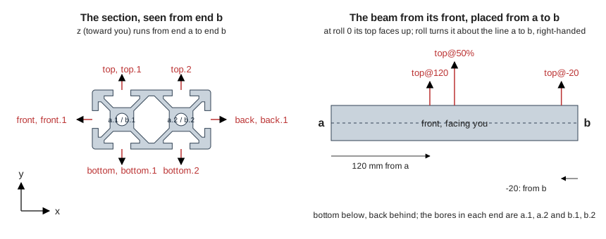
|
39
|
+
dimensions a hole (`drillGuideModel`), a tap guide over an end (`tapGuideModel`), a cut-length stop with its gauge
|
|
40
|
+
(`lengthStopModel`) and a squaring corner (`squareCornerModel`).
|
|
41
|
+
|
|
42
|
+
A whole frame from these, a box of 2020 with a motor-driven axis, cut, drilled, printed on one plate and built in
|
|
43
|
+
order, is chapter 16 of [the worked examples](https://github.com/JoniBach/rulecad/blob/main/packages/cad/EXAMPLES.md).
|
|
44
|
+
More fittings (a three-way corner, a hidden-corner cover, a printed node) and a belt drive follow in later releases.
|
|
45
|
+
The plan is [issue 240](https://github.com/JoniBach/rulecad/issues/240).
|
|
46
|
+
|
|
47
|
+
```sh
|
|
48
|
+
npm install @rulecad/frames @jscad/modeling
|
|
49
|
+
```
|
|
50
|
+
|
|
51
|
+
It depends on `@rulecad/rules`, where the profiles live as open data, `@rulecad/fixings`, which sizes anything an
|
|
52
|
+
operation names by a thread, and `@rulecad/fea`, which bends a printed fitting under its load. It takes JSCAD (`@jscad/modeling`, which a
|
|
53
|
+
rulecad design already has) as a peer for a beam's solid.
|
|
54
|
+
|
|
55
|
+
## A profile
|
|
9
56
|
|
|
10
57
|
```js
|
|
11
|
-
import {
|
|
12
|
-
|
|
58
|
+
import { profileModel, outline, section, profiles } from '@rulecad/frames'
|
|
59
|
+
|
|
60
|
+
profiles() // ['profile-2020-bosch', 'profile-2020-generic', 'profile-2020-misumi-hfs5', …]
|
|
61
|
+
const p = profileModel('2020-misumi-hfs5') // MISUMI's HFS5-2020, by its set's name with or without 'profile-'
|
|
62
|
+
|
|
63
|
+
p.width, p.height, p.cornerRadius // 20, 20, 1
|
|
64
|
+
p.faces.top // [{ face: 'top', index: 1, slot: 'slot-6-misumi', at: [0, 10], normal: [0, 1], along: [1, 0] }]
|
|
65
|
+
p.slots['slot-6-misumi'].opening // 6
|
|
66
|
+
p.bores[0] // { at: [0, 0], diameter: 4.2, thread: 'M5', threadSet: 'm5', tapDrill: 4.2, … }
|
|
67
|
+
p.sheet.area // 183: the catalogue's figure, mm²
|
|
68
|
+
p.figures.area // { value: 183, unit: 'mm²', kind: 'spec', source: 'MISUMI … page 2-529, https://…', … }
|
|
69
|
+
p.material.modulus // 69972 MPa, from the al6n01-t5 rule set the profile names
|
|
70
|
+
|
|
71
|
+
const s = section(p)
|
|
72
|
+
s.area, s.inertiaX, s.torsion // 182.5 mm², 7425 mm⁴, 809 mm⁴: from the drawn outline
|
|
73
|
+
s.sheet.area // { sheet: 183, computed: 182.5, difference: -0.003 }
|
|
74
|
+
outline(p).loops // [[[x, y], …] the outside, counter-clockwise, then each hole clockwise]
|
|
13
75
|
```
|
|
14
76
|
|
|
15
|
-
|
|
77
|
+
A section is drawn in x (across, its width) and y (up, its height) with the middle of its envelope at the origin.
|
|
78
|
+
The beam runs along z. Its faces are `top` (+y), `bottom` (-y), `front` (-x) and `back` (+x), and the slots of a face
|
|
79
|
+
count from 1 along +x or +y. Lengths are in mm, areas mm², second moments and the torsion constant mm⁴, mass kg/m.
|
|
16
80
|
|
|
17
|
-
|
|
18
|
-
and channel, each from its maker's sheet with its sources, plus any section of your own.
|
|
19
|
-
- **Beams.** A profile and a length, with an address for any point along any face, so things attach by saying
|
|
20
|
-
where.
|
|
21
|
-
- **Joins that do their own drilling.** Say how two beams are joined (a blind joint, a bracket, a gusset) and the
|
|
22
|
-
tapped ends, access holes, fittings and screws follow.
|
|
23
|
-
- **Fittings drawn from the profile's rules.** Brackets, feet, panel clips, mounts and slot-nut carriers that print
|
|
24
|
-
without supports, with bought ones as an alternative.
|
|
25
|
-
- **Guides.** Linear rails, V-wheels, rods and printed sliders on a beam, each an ordinary sliding joint.
|
|
26
|
-
- **Printed beams**, with profiles that print lying down and still take a standard slot nut.
|
|
81
|
+
### The model
|
|
27
82
|
|
|
28
|
-
|
|
29
|
-
|
|
83
|
+
| Field | What |
|
|
84
|
+
|---|---|
|
|
85
|
+
| `kind`, `name`, `family` | `'profile'`, the set's name, and what sort of section: `t-slot`, `v-slot`, `tube`, `round-tube`, `angle`, `channel`, `bar`, `round-bar`, `custom`, `printed` |
|
|
86
|
+
| `series`, `cells`, `pitch` | The base size, the cells as `[across, up]`, and the size of one cell as `[x, y]` |
|
|
87
|
+
| `width`, `height`, `cornerRadius`, `wall` | The envelope, and a tube's, angle's or channel's wall |
|
|
88
|
+
| `faces` | `top`, `bottom`, `front`, `back`: each a list with one entry per cell along it, `{ face, index, slot, at, normal, along }`. `slot` is a slot family's name, or `null` where the face is closed there |
|
|
89
|
+
| `slots` | The slot families it uses, by name: `{ opening, mouth, lip, lipAngle, cavityWidth, cavityDepth, floorWidth, flankAngle, straight, trackWidth, trackAngle, nutFamily, figures }` |
|
|
90
|
+
| `bores` | Each bore: `{ at, diameter, thread, threadSet, tapDrill, major, threadPitch, where }`, `where` being `cell`, `corner` or `given` |
|
|
91
|
+
| `title` | A line for a list: `'25 x 25 x 2 tube, al6063-t5'`, `'20 x 20 t-slot (profile-2020-misumi-hfs5)'` |
|
|
92
|
+
| `chambers`, `hollows` | The closed hollow where two cells meet (`{ at, axis, width, length, depth, ends, slot }`: `ends` are its half widths toward each end, narrower toward a place where four cells meet), and square hollows in the corners of a lighter section |
|
|
93
|
+
| `sheet` | What the sheet says: `{ area, inertiaX, inertiaY, modulusX, modulusY, torsion, massPerMetre }`, `null` where it gives none |
|
|
94
|
+
| `material` | The material set it names: `{ name, alloy, density, modulus, poisson, strength, figures }`, or `null` |
|
|
95
|
+
| `supply` | `{ lengths, cutMin, cutMax, cutTolerance, straightness, twist }` |
|
|
96
|
+
| `figures` | Every rule of the set by name, each `{ value, unit, kind, source, rule, checked }` |
|
|
97
|
+
| `measured` | A measured outline, when one was handed in |
|
|
98
|
+
| `rests` | The kinds its figures and its slots' rest on: `['spec', 'estimate']` |
|
|
30
99
|
|
|
31
|
-
|
|
100
|
+
`profileModel(which, change, given)` takes a second argument to change a figure (`{ bore_diameter: 5 }`, or
|
|
101
|
+
`{ area: { value: 180, kind: 'measured', source: 'weighed a metre' } }`), and a third for what is not in the
|
|
102
|
+
catalogue: `{ sets: { 'my-slot': {…} } }` or `{ load: (name) => set }` for a slot family, thread or material of your
|
|
103
|
+
own, and `{ outline: {…} }` for a measured outline. A profile of your own is a rule set handed in place of the name.
|
|
104
|
+
|
|
105
|
+
### Cells and faces
|
|
106
|
+
|
|
107
|
+
A larger section is cells of its series. A 40 x 20 has `cells_across` 2 and `cells_up` 1 in its rule set, and the
|
|
108
|
+
model expands them: two slots on each wide face, one on each end, a bore in the middle of each cell and one closed
|
|
109
|
+
hollow where the two cells' slots would have met. Each sold profile is its own rule set with its own sheet's figures.
|
|
110
|
+
A face is overridden in the rule set: `"slot_bottom": "closed"` for a smooth face, `"slot_top": "slot-6, closed"` for
|
|
111
|
+
one slot of two, another family's name to mix two slots in one section.
|
|
112
|
+
|
|
113
|
+
A grid need not be full. `cells_absent` names the cells that are not there, as across,up pairs from 1 at the lower
|
|
114
|
+
left: OpenBuilds' C-Beam is 4 cells by 2 with `"2,2; 3,2"` absent. `faces` then holds a place for every side of a cell
|
|
115
|
+
with no cell beyond it, by the way it looks: `faces.top` of a C-beam has four places, two on top of the arms and two on
|
|
116
|
+
the floor of the C lower down, and `faces.back` has the inside of the left arm beside the right-hand outside. `index`
|
|
117
|
+
is the place's column (top and bottom) or row (front and back). Where four cells meet, or a cell stands at a corner of
|
|
118
|
+
a missing one, the hollows between cells keep to the cavity's own width (`ends`), so they stand clear of each other.
|
|
119
|
+
|
|
120
|
+
### Outlines
|
|
121
|
+
|
|
122
|
+
`outline(model)` returns `{ loops, measured, source }`. Each loop is a closed list of `[x, y]` points: the outside of
|
|
123
|
+
the metal first, counter-clockwise, with every open slot cut into it, then each hole clockwise (bores, hollows, a
|
|
124
|
+
tube's inside). It is drawn from the interface dimensions alone: the envelope and its corner radius, each slot from
|
|
125
|
+
its opening, lip, cavity width and depth, floor width and flank angle, and each bore as a circle of the same area. It
|
|
126
|
+
leaves out what those dimensions do not say: fillets, the notches round some makers' bores, grooves and ribs.
|
|
127
|
+
|
|
128
|
+
A measured outline takes its place when you have one: `readOutline(json)` holds a file to its format (a `source`, a
|
|
129
|
+
`licence`, and `loops` in mm) and turns every loop the right way round. In a workspace it is the file
|
|
130
|
+
`rules/outlines/<set name>.json`. The kit publishes no maker's outline. It draws its own, and a maker's model is
|
|
131
|
+
measured in your own workspace.
|
|
132
|
+
|
|
133
|
+
### Plain sections: a family and a size
|
|
134
|
+
|
|
135
|
+
Tube, round tube, angle, channel, flat bar and round bar have no maker's sheet. Each is a family with a base set
|
|
136
|
+
(`profile-tube`, `profile-round-tube`, `profile-angle`, `profile-channel`, `profile-bar`, `profile-round-bar`) that
|
|
137
|
+
holds a starting size, and any other size is the family's name with the figures you have:
|
|
138
|
+
|
|
139
|
+
```js
|
|
140
|
+
const tube = profileModel('tube', { width: 25, height: 25, wall: 2, material: 'al6063-t5' });
|
|
141
|
+
tube.title; // '25 x 25 x 2 tube, al6063-t5'
|
|
142
|
+
section(tube).area; // 184 mm²: 25² less 21²
|
|
143
|
+
beamFigures(tube).torsion; // { value: 25410, unit: 'mm⁴', kind: 'derived', from: 'outline', source }
|
|
144
|
+
profileModel('angle', { width: 40, height: 25, wall: 3, material: 's275' }); // unequal legs, in steel
|
|
145
|
+
profileModel('round-bar', { width: 12, height: 12 }); // a round section's width and height are its diameter
|
|
146
|
+
```
|
|
147
|
+
|
|
148
|
+
| Family | `width` | `height` | `wall` | Also |
|
|
149
|
+
|---|---|---|---|---|
|
|
150
|
+
| `tube` | Outside, across | Outside, up | The wall, all round | `corner_radius` outside (cold-formed steel tube is rounded by about twice its wall) |
|
|
151
|
+
| `round-tube` | Outside diameter | The same | The wall | |
|
|
152
|
+
| `angle` | The leg along the bottom | The leg up the side | Both legs' thickness | The legs meet at the lower left |
|
|
153
|
+
| `channel` | Across the web | The flanges' height | Web and flanges | The web is along the bottom |
|
|
154
|
+
| `bar` | Across | Thickness | none | |
|
|
155
|
+
| `round-bar` | Diameter | The same | none | |
|
|
156
|
+
|
|
157
|
+
`material` is a material set's name (`al6063-t5`, `s275`, or one of your own through `given`), and gives the mass per
|
|
158
|
+
metre. A few common sizes are ready sets, named for what they are (`profile-tube-al-25x25x2`,
|
|
159
|
+
`profile-angle-steel-30x30x3`): each is its family at that size, for a workspace that wants a name to point at.
|
|
160
|
+
|
|
161
|
+
`beamFigures(model)` gives the figures to design a beam with, whatever the profile: the sheet's own where the maker
|
|
162
|
+
prints one (`from: 'sheet'`, with the sheet's kind and source), and the outline's where it does not (`kind:
|
|
163
|
+
'derived'`, `from: 'outline'`). A plain section's are all worked out; MISUMI prints no torsion constant, so that one
|
|
164
|
+
figure of an HFS profile is worked out and the rest are the page's.
|
|
165
|
+
|
|
166
|
+
### A custom section
|
|
167
|
+
|
|
168
|
+
Family `custom` is any closed outline. A custom profile is its outline: the set gives the family, the envelope and
|
|
169
|
+
the material, and the outline comes with it, as `rules/outlines/<set name>.json` in a workspace or handed in:
|
|
170
|
+
|
|
171
|
+
```js
|
|
172
|
+
const hat = { source: 'traced from my own bar', licence: 'my own measurement',
|
|
173
|
+
loops: [[[-20, -10], [-10, -10], [-10, 8], [10, 8], [10, -10], [20, -10], [20, -8], [12, -8], [12, 10], [-12, 10], [-12, -8], [-20, -8]]] };
|
|
174
|
+
const mine = profileModel('custom', { width: 40, height: 20, material: 's275' }, { outline: hat });
|
|
175
|
+
section(mine).area; // 152 mm²
|
|
176
|
+
```
|
|
177
|
+
|
|
178
|
+
`profileModel('custom')` alone is the kit's own example, a 30 x 30 x 3 mm T section drawn for the kit. A custom set
|
|
179
|
+
with no outline is refused by name, and a check says where an outline's envelope is not the set's width and height
|
|
180
|
+
(`profile.outline.size`) or is not drawn about its own middle (`profile.outline.middle`).
|
|
181
|
+
`cad measure <model> --profile <name>` writes the set and the outline from a model or a DXF.
|
|
182
|
+
|
|
183
|
+
### What a check finds
|
|
184
|
+
|
|
185
|
+
`profileFindings(model)` returns findings in rulecad's one shape, `{ level, code, text, rule, at, values }`:
|
|
186
|
+
|
|
187
|
+
| Code | Level | When |
|
|
188
|
+
|---|---|---|
|
|
189
|
+
| `profile.slot.fit` | fail | A slot or hollow reaches outside the section, or runs into another: no metal is left between them |
|
|
190
|
+
| `profile.bore.clear` | fail | A bore breaks into a slot, a hollow or another bore |
|
|
191
|
+
| `profile.bore.tap` | fail | The bore is as wide as the thread it is tapped to |
|
|
192
|
+
| | warn | The bore is under the thread's root, or leaves under a quarter of its height: probably the wrong thread |
|
|
193
|
+
| | info | The bore leaves under half a thread's height, as some makers' bores do |
|
|
194
|
+
| `profile.bore.thread` | warn | The thread named is no thread set, so nothing was compared |
|
|
195
|
+
| `profile.section.area` and `.mass_per_metre` | warn | The sheet's figure and the outline's differ by more than 5% |
|
|
196
|
+
| `profile.section.inertia_x` and `.inertia_y` | warn | By more than 10% |
|
|
197
|
+
| `profile.section.torsion_constant` | warn | By more than 15% |
|
|
198
|
+
| `profile.outline.size` | warn | A measured outline's envelope is more than 0.2 mm from the set's width or height |
|
|
199
|
+
| `profile.outline.middle` | warn | A measured outline is not drawn about the middle of its envelope |
|
|
200
|
+
|
|
201
|
+
The allowances are in `DEFAULTS`, each with the sentence it rests on. They are estimates: a section drawn from a
|
|
202
|
+
fully dimensioned slot comes within them (MISUMI's eight profiles are within 4% on area and 6% on second moments),
|
|
203
|
+
and one outside them has a dimension wrong or a shape the dimensions do not describe, such as the L-shaped hollows of
|
|
204
|
+
a light 40 mm section. A warning is a reason to look, and the sheet's figure stays the one to design with.
|
|
205
|
+
|
|
206
|
+
## A beam
|
|
207
|
+
|
|
208
|
+
A beam is a length of a profile. It lies along z: end `a` at z = 0, end `b` at z = its length, its section in x and y
|
|
209
|
+
as the profile draws it.
|
|
210
|
+
|
|
211
|
+
```js
|
|
212
|
+
import { beamModel, beam, beamAnchor, printable } from '@rulecad/frames'
|
|
213
|
+
|
|
214
|
+
const b = beamModel('2040-misumi-hfs5', { length: 300 })
|
|
215
|
+
b.mass // 264.3 g: the drawn section's 326.2 mm² x 300 mm x 2.7 g/cm³
|
|
216
|
+
b.weight // { computed: 264.3, sheet: 264, difference: 0.001 }: the sheet's 0.88 kg/m
|
|
217
|
+
b.centreOfMass // [0, 0, 150]
|
|
218
|
+
b.figures.inertiaX // { value: 13580, unit: 'mm⁴', kind: 'spec', from: 'sheet', source: 'MISUMI …' }
|
|
219
|
+
b.anchors['top.2'] // { origin: [10, 10, 150], axis: [0, 1, 0], ref: [0, 0, 1] }
|
|
220
|
+
beamAnchor(b, 'top.2@-20') // the same place 20 mm from end b: origin [10, 10, 280]
|
|
221
|
+
|
|
222
|
+
beam(b, { display: 'link' }) // a plain 40 x 20 x 300 box: 12 triangles
|
|
223
|
+
beam(b) // the true section run 300 mm (display: 'preview', the default)
|
|
224
|
+
printable(b) // [{ level: 'fail', code: 'beam.printable', text: '… is a bought beam …' }]
|
|
225
|
+
```
|
|
226
|
+
|
|
227
|
+
`beamModel(profile, { length, ends, material, given, cells })` takes a profile's model or anything `profileModel`
|
|
228
|
+
takes, and:
|
|
229
|
+
|
|
230
|
+
| Option | What |
|
|
231
|
+
|---|---|
|
|
232
|
+
| `length` | mm from end `a` to end `b`. Required |
|
|
233
|
+
| `ends` | Each end `cut` square (the default) or `tapped`, its bores carrying the profile's `bore_thread`: one word for both, `[a, b]`, or `{ a, b }`. Mitres and drilling are operations on a beam, in a later release |
|
|
234
|
+
| `material` | A material set's name in place of the profile's alloy, to weigh the same frame in another metal or a plastic. The sheet's mass is then not compared |
|
|
235
|
+
| `given` | `profileModel`'s third argument: slot families, threads and materials of your own |
|
|
236
|
+
| `cells` | Raster cells for the torsion constant, where the sheet gives none |
|
|
237
|
+
|
|
238
|
+
The model:
|
|
239
|
+
|
|
240
|
+
| Field | What |
|
|
241
|
+
|---|---|
|
|
242
|
+
| `kind`, `name`, `title` | `'beam'`, `'profile-2040-misumi-hfs5 x 300'`, and a line for a list |
|
|
243
|
+
| `profile`, `length`, `ends` | The profile's model, the length, and each end's `{ kind, thread }` |
|
|
244
|
+
| `material` | `{ name, density, modulus, given }`, `given` true where the option changed it |
|
|
245
|
+
| `area`, `centroid` | The section's, from its outline |
|
|
246
|
+
| `mass`, `centreOfMass` | Grams from the section's area, the length and the material's density; the section's centroid at half the length |
|
|
247
|
+
| `weight` | `{ computed, sheet, difference }`: the mass beside the sheet's mass per metre times the length |
|
|
248
|
+
| `figures` | `beamFigures(profile)`: the figures to design with, the sheet's where it gives one |
|
|
249
|
+
| `places` | Every place a face offers, `{ name, face, index, slot, at, normal, along, depth }`: `slot` is `null` on a closed face, `depth` the slot's cavity depth |
|
|
250
|
+
| `bores` | Each bore in each end, `{ name, end, at, diameter, thread, tapped }` |
|
|
251
|
+
| `anchors` | By name, each `{ origin, axis, ref }` (below) |
|
|
252
|
+
| `bought`, `printed` | `true` and `false`: a beam of a profile is cut from stock |
|
|
253
|
+
| `findings` | `beam.mass` (info: the mass and how it was worked out; warn: more than 5% from the sheet's), `beam.length` (warn: longer than the profile is sold or cut in, or shorter than the maker cuts) |
|
|
254
|
+
|
|
255
|
+
### Anchors and addresses
|
|
256
|
+
|
|
257
|
+
Each anchor is a point (`origin`), the direction out of the beam there (`axis`), and a direction square to it that
|
|
258
|
+
fixes the turn about it (`ref`): at an end the beam's up (+y), on a face along the beam toward end `b` (+z).
|
|
259
|
+
|
|
260
|
+
| Address | Where |
|
|
261
|
+
|---|---|
|
|
262
|
+
| `a`, `b` | The middle of each end, `axis` out of the end |
|
|
263
|
+
| `a.1`, `b.2` | The bores in each end, numbered as `profile.bores` lists them |
|
|
264
|
+
| `top`, `top.1`, `top.2` | The places on a face, counted along it (+x for top and bottom, +y for front and back). `top` is the first. A face with one place has `top` and `top.1`. A place's anchor is where it meets the face, at half the length, `axis` out of the face |
|
|
265
|
+
| `top@120`, `top@-20`, `top@50%` | With `beamAnchor`: 120 mm from end `a`, 20 mm from end `b`, the middle. A distance past an end is refused with the beam's length |
|
|
266
|
+
|
|
267
|
+
A section with cells missing (OpenBuilds' C-Beam) has places inside its C on the same faces: they are numbered after
|
|
268
|
+
the outside places of the same column or row, and `index` says which column or row each is in. Place by `origin` and
|
|
269
|
+
`axis`, never by the number alone.
|
|
270
|
+
|
|
271
|
+
### Face names in an assembly
|
|
272
|
+
|
|
273
|
+
|
|
274
|
+
|
|
275
|
+
The face names belong to the beam, so they turn with it. In a cad assembly a beam placed by its ends (`"from"`,
|
|
276
|
+
`"to"`) has end `a` at `from` and end `b` at `to`. At roll 0 its top faces up (+z), or +y when the beam stands upright
|
|
277
|
+
(within 0.1° of z). Looking along the beam from `a` to `b` with its top up, its front is on the right and its back on
|
|
278
|
+
the left: a beam run along +x has its front toward -y, facing a viewer in front of it. `"roll"` turns the beam about
|
|
279
|
+
the line from `a` to `b` by that many degrees, right-handed, and the faces turn with it: at roll 90 the top of a beam
|
|
280
|
+
run along +x faces -y.
|
|
281
|
+
|
|
282
|
+
In an assembly an address names the item first: `x1.a`, `x1.a.1`, `x1.top@120`, `x1.top.2@-20`, `x1.top@50%`. A place's
|
|
283
|
+
anchor has its z out of the face and its x along the beam toward `b`, so a part placed at an address sits on the face
|
|
284
|
+
with its own x along the beam. The cad README says where addresses are taken.
|
|
285
|
+
|
|
286
|
+
### Operations
|
|
287
|
+
|
|
288
|
+
A beam carries a list of operations, `ops`, each a line on its cut-and-drill sheet and a cut in its solid. Each is
|
|
289
|
+
placed by an address on the beam: an end (`a`, `b`), an end's bore (`a.1`), or a face's place with a distance from
|
|
290
|
+
end a (`top@120`, `top@-20` from end b, `top@50%`).
|
|
291
|
+
|
|
292
|
+
```js
|
|
293
|
+
const b = beamModel('2020-misumi-hfs5', { length: 300, ops: [
|
|
294
|
+
{ op: 'tap', at: 'a', thread: 'M5' }, // M5 in end a's bore, 10 mm deep: 2 diameters for aluminium
|
|
295
|
+
{ op: 'access', at: 'top@-10', thread: 'M5' }, // a Ø5.3 mm hole 10 mm from end b, for an M5 cap screw's 4 mm key
|
|
296
|
+
] });
|
|
297
|
+
b.ops.map((o) => o.line); // 'tap M5 in bore a.1, 10 mm deep (tap drill Ø4.2 mm; the bore is Ø4.2)', 'cut end a square', ...
|
|
298
|
+
```
|
|
299
|
+
|
|
300
|
+
| Operation | What it is | Where | Takes |
|
|
301
|
+
|---|---|---|---|
|
|
302
|
+
| `cut` | A square cut to length. Each end with no cut or mitre of its own gets one (`implied: true`) | `a`, `b` | |
|
|
303
|
+
| `mitre` | An end cut at an angle from square, seen on a named face | `a`, `b` | `angle` (above 0, under 90), `about` (the face), `long` (the side the length is on) |
|
|
304
|
+
| `tap` | A thread cut in an end bore. `ends: 'tapped'` is the same | `a`, `b`, `a.1` | `thread` (default the profile's `bore_thread`), `depth` |
|
|
305
|
+
| `access` | A hole across the beam, in line with a slot, through its floor, for a key | a face | `thread` (sizes it for that screw's key) and `head` (the head the key turns: `cap`, the default, `button` or `countersunk`), or `diameter`; `depth`, `through` (`wall`, the default, or `beam`: every wall on its line, to the slot on the far side) |
|
|
306
|
+
| `drill` | A hole through one wall or right through, plain or tapped | a face | `thread` and `kind` (clearance, close, loose, tap) or `diameter`; `through` (`wall`, the default, or `beam`); `depth` |
|
|
307
|
+
| `counterbore` | A seat for a head in a face, with the screw's hole through the wall | a face | `thread`, `head`, `diameter`, `depth` |
|
|
308
|
+
| `pocket` | A milled pocket | a face | `size` (`[along, across]`) or `outline` (points about the address), `radius`, `depth` |
|
|
309
|
+
| `notch` | Part of a slot's lips cut away, to load a nut mid-span | a face with a slot | `length` |
|
|
310
|
+
| `deburr` | Named so the sheet asks for it | `a`, `b` | |
|
|
311
|
+
|
|
312
|
+
Sizes named by a thread come from `@rulecad/fixings` as a machine cuts them: the thread's figure as drawn, with no
|
|
313
|
+
printer's hole compensation and no teardrop roof. An access hole is the smallest of the thread's clearance holes
|
|
314
|
+
wider than its hex key across the corners, the key of the head it is for (an M5 cap screw's is 4 mm, an M5 button
|
|
315
|
+
head's 3 mm). A counterbore leaves `OP_DEFAULTS.seat` round the head. A hole through one
|
|
316
|
+
wall goes as deep as the first run of metal along its line through the section, worked out from the outline.
|
|
317
|
+
|
|
318
|
+
Each worked-out operation in `model.ops` keeps its `distance` from end a (0 and the length for the ends), its `face`
|
|
319
|
+
and `place` (`top.1`), its frame (`anchor`), its sizes, and `line`, its line on the sheet. They are in order along the
|
|
320
|
+
beam. In the solid, a tapped length is drawn over the thread's roots (its major diameter), so a screw drawn whole fits
|
|
321
|
+
it; the holes, pockets and notches are cut from the preview, and a mitre from the link as well, since it changes the
|
|
322
|
+
envelope an overlap check measures.
|
|
323
|
+
|
|
324
|
+
**A mitre** is measured on its long side: the beam's `length` is the long side's, and the mitre says so, with the
|
|
325
|
+
short side's length (`shortLength`). `{ op: 'mitre', at: 'a', angle: 45, about: 'top' }` on a 2040 cuts end a so that,
|
|
326
|
+
seen from the top, the back is the long side (the default; `long: 'front'` for the other way) and the front is 40 mm
|
|
327
|
+
shorter.
|
|
328
|
+
|
|
329
|
+
**What a check finds** (`beam.op`): a hole wider than a slot's opening, which breaks into its lips (and the far slot's,
|
|
330
|
+
right through); a hole that cuts into the side of a bore; a tap deeper than the bore runs, or taps from both ends that
|
|
331
|
+
meet; a hole that crosses a tapped thread; a hole whose edge leaves less than half its diameter of metal to an end
|
|
332
|
+
(`OP_DEFAULTS.edge`, warn), or runs off it (fail). Thread engagement is `@rulecad/fixings`' `engagement` in the beam's
|
|
333
|
+
alloy: a thread tapped in a 1.9 mm slot floor gets a warning that aluminium wants 2 diameters. Refused by name: an
|
|
334
|
+
operation the kit does not have, a key it does not take, an address of the wrong kind, a tap in a profile with no end
|
|
335
|
+
bore, a thread too small for the bore, two cuts at one end, a mitre that leaves no short side, and any operation on a
|
|
336
|
+
printed profile (they become features of the print in a later release).
|
|
337
|
+
|
|
338
|
+
### The solid
|
|
339
|
+
|
|
340
|
+
`beam(m, { display })` takes a beam's model, or a profile with the options `beamModel` takes. `display: 'link'` is a
|
|
341
|
+
plain box of the section's envelope (a round section is a twelve-sided prism), 12 triangles, for a link and an
|
|
342
|
+
overlap check. `'preview'` is the true section, every slot, bore and hollow, run the whole length: 872 triangles for a
|
|
343
|
+
2040. `tracks: true` cuts each V track from a link's box along the beam (the V mouth, and the opening under it to the
|
|
344
|
+
cavity's depth), so a V-wheel's rim running in its track is clear of it and a rim out of its track is not; on a beam
|
|
345
|
+
with no V track it is the plain box. The solid carries `.model` (the beam's model) and `.display`.
|
|
346
|
+
|
|
347
|
+
### Mass beside the sheet
|
|
348
|
+
|
|
349
|
+
The mass is worked out from the section and the alloy, so it says what the drawn or measured outline weighs. For a
|
|
350
|
+
section whose slots are fully dimensioned it comes within 2% of the sheet. A 300 mm 40 x 20, by maker:
|
|
351
|
+
|
|
352
|
+
| Profile | Mass, g | Sheet, g | Difference | Ix against the sheet | Iy against the sheet |
|
|
353
|
+
|---|---|---|---|---|---|
|
|
354
|
+
| MISUMI HFS5-2040 | 264.3 | 264 | +0.1% | +0.9% | 0.0% |
|
|
355
|
+
| item Profile 8 40x20 Line 5 | 264.6 | 267 | -0.9% | +0.2% | -0.3% |
|
|
356
|
+
| Bosch Rexroth 20x40 | 243.8 | 240 | +1.6% | +1.7% | +4.2% |
|
|
357
|
+
|
|
358
|
+
Light 40 mm sections (Bosch Rexroth 40x40L, item's light Line 8, Motedis I-type light, generic I-type 4040) have
|
|
359
|
+
hollows and hooked lips the dimensions do not describe, and come out 8 to 21% heavy. Their beams say so
|
|
360
|
+
(`beam.mass`, warn) and name the sheet's mass to use instead; their `figures` are the sheet's.
|
|
361
|
+
|
|
362
|
+
`printable(x)` takes a beam's model, its solid or a profile's model, and fails it: a beam of a profile is bought and
|
|
363
|
+
cut, and what prints is the parts that fasten to it. Printed beams come in a later release.
|
|
364
|
+
|
|
365
|
+
## The cut list
|
|
366
|
+
|
|
367
|
+
A frame's beams, listed for the saw: `cutList(beams, { kerf?, trim?, tolerance?, stock? })` takes beams' models, or
|
|
368
|
+
`{ id, beam }` with each item's name.
|
|
369
|
+
|
|
370
|
+
```js
|
|
371
|
+
import { beamModel, cutList, cutListText, beamSheet } from '@rulecad/frames';
|
|
372
|
+
|
|
373
|
+
const beams = [300, 300, 260, 260].map((length, i) => ({ id: `x${i + 1}`, beam: beamModel('2020-misumi-hfs5', { length }) }));
|
|
374
|
+
const c = cutList(beams);
|
|
375
|
+
cutListText(c); // the marks, then each profile's lengths, bars to buy and the cuts on each
|
|
376
|
+
beamSheet(c.marks[0].beam, { mark: 'A', items: c.marks[0].items }).svg; // its cut-and-drill sheet
|
|
377
|
+
```
|
|
378
|
+
|
|
379
|
+
Beams that are the same (one profile, one material, one length, and the same operations at the same places) share a
|
|
380
|
+
**mark**, A, B, C and on, by profile and then the longest first. Each mark in `c.marks` has `mark`, `profile`,
|
|
381
|
+
`material`, `length` (the long side where an end is mitred) and `shortLength`, `count`, `items`, `grams` each and
|
|
382
|
+
`weighedBy` (`sheet` where the maker gives a mass per metre, else `section`: a light 40 mm section is heavy when
|
|
383
|
+
weighed from its drawn outline), `ops` (each operation in a few words) and `beam` (the model).
|
|
384
|
+
|
|
385
|
+
Each profile's beams are packed into the lengths it is sold in (`lengths` in its set). Every cut takes the saw's
|
|
386
|
+
**kerf**, the last one on a bar too, as it parts the beam from the offcut. The first end of every bar is **trimmed**
|
|
387
|
+
square before the first beam is measured. Where a set gives no lengths but a cut-to-length range, the maker cuts each
|
|
388
|
+
beam and no bar is packed (`supply: 'cut'`). Where it gives neither, a 6 m bar is assumed (`supply: 'assumed'`, an
|
|
389
|
+
estimate). Each entry in `c.stock` has `cuts` (each length and how many), `buy` (each bar length and how many),
|
|
390
|
+
`bars` (each with its `cuts` in order, each cut's `at` measured from the bar's first end, and its `offcut`),
|
|
391
|
+
`unpacked`, `bought` and `offcut` in mm.
|
|
392
|
+
|
|
393
|
+
The packing is **first-fit decreasing**, a simple rule that does not always find the fewest bars: the longest beam
|
|
394
|
+
first, each onto the first bar with room for it, else onto a new bar. It runs once with each sold length as the new
|
|
395
|
+
bar's length (and once with the shortest that holds the beam), then cuts each bar down to the shortest sold length
|
|
396
|
+
that holds what is on it, and keeps the plan that buys the least metal, then the fewest bars. `packBars(pieces,
|
|
397
|
+
lengths, { kerf, trim })` is the packing alone. A box of twelve 2020 beams (four each of 300, 260 and 220 mm) buys
|
|
398
|
+
one 4000 mm MISUMI bar with an 834 mm offcut: four 1000 mm bars are also 4000 mm of metal, so the one bar wins.
|
|
399
|
+
|
|
400
|
+
| Rule (`CUT_DEFAULTS`) | Value | Kind | Source |
|
|
401
|
+
|---|---|---|---|
|
|
402
|
+
| `kerf` | 3 mm | default | A 250 mm, 80-tooth carbide blade for non-ferrous metals (Popular Tools NF2503080) cuts 3.0 mm |
|
|
403
|
+
| `trim` | 10 mm | estimate | A working allowance for a bruised or out-of-square mill end; no supplier's figure was found |
|
|
404
|
+
| `tolerance` | ±0.5 mm | estimate | MISUMI's for its cut lengths, used where a profile's set gives no `cut_tolerance` |
|
|
405
|
+
| `stock` | 6000 mm | estimate | The length Bosch Rexroth and item sell their profiles in, used where a set gives no lengths |
|
|
406
|
+
|
|
407
|
+
Give your own saw's figures as options (`cutList(beams, { kerf: 2.4 })`); `c.rules` holds the rules used, each with
|
|
408
|
+
`value`, `unit`, `rule`, `kind`, `source` and `checked`.
|
|
409
|
+
|
|
410
|
+
The checks (`c.findings`, code `frame.cut`):
|
|
411
|
+
|
|
412
|
+
| Level | When |
|
|
413
|
+
|---|---|
|
|
414
|
+
| fail | A beam longer than any length its profile is sold in, after the trim and one kerf, or than the maker cuts to |
|
|
415
|
+
| warn | Two marks of one profile whose lengths differ by less than two cuts' tolerance: they should match, or the saw cannot hold them apart |
|
|
416
|
+
| info | Two or more beams of one mark: each is cut to the tolerance, so they can differ by twice it; cut them against one stop where they must match |
|
|
417
|
+
|
|
418
|
+
### A cut-and-drill sheet
|
|
419
|
+
|
|
420
|
+
`beamSheet(beam, { mark, items, grams })` draws one SVG sheet for a beam, in mm, so it prints to scale at 100%. The
|
|
421
|
+
beam is drawn 1:1, 1:2, 1:5, 1:10 and on, the smallest that keeps it within 200 mm, and its section at end a at 4:1,
|
|
422
|
+
2:1 or 1:1. On it: the section seen from end a with top up and each face named, and each tapped bore with its thread
|
|
423
|
+
and depth; a view of each face that has work on it, or a mitre seen from it, with that face up and end a on the left,
|
|
424
|
+
every slot's centre line, and each operation numbered and dimensioned from end a to 0.1 mm; and the operations in
|
|
425
|
+
order from end a, each with its full line. A face only a few mm wide at a small scale is drawn wider across, and the
|
|
426
|
+
view says by how much. It returns `{ svg, scale, faces, dimensions }`, `dimensions` being each operation's figure as
|
|
427
|
+
the sheet prints it.
|
|
428
|
+
|
|
429
|
+
## Joins
|
|
430
|
+
|
|
431
|
+
A join names an end of one beam (`a`) and a place on another (`b`): a face with a distance from b's end a where
|
|
432
|
+
a's end meets it (`back@120`), or b's end for beams that meet end to end or at a corner. `joinModel` works out what
|
|
433
|
+
each kind of join does to both beams, the screws that hold it, and the stiffness it is taken to have.
|
|
434
|
+
|
|
435
|
+
```js
|
|
436
|
+
import { beamModel, joinModel } from '@rulecad/frames'
|
|
437
|
+
|
|
438
|
+
const post = beamModel('2020-misumi-hfs5', { length: 200 }), rail = beamModel('2020-misumi-hfs5', { length: 300 })
|
|
439
|
+
const j = joinModel('blind', { beam: post, end: 'a' }, { beam: rail, address: 'back@120' })
|
|
440
|
+
|
|
441
|
+
j.a.ops // [{ op: 'tap', at: 'a.1', thread: 'M5', depth: 18.5 }]: the post's end bore tapped M5
|
|
442
|
+
j.b.ops // [{ op: 'access', at: 'front.1@120', thread: 'M5', head: 'button', through: 'beam' }]: a hole for the button head's 3 mm key, across the rail
|
|
443
|
+
j.screws // [{ screw: 'M5 button', thread: 'M5', head: 'button', bore: 'a.1' }]
|
|
444
|
+
j.stiffness // { bending: 1500000, twist: 300000, end: { rx: 300000, ry: 1500000, rz: 1500000 }, kind: 'estimate', … }
|
|
445
|
+
|
|
446
|
+
beamModel(rail.profile, { length: 300, ops: j.b.ops }) // the rail with its access hole: Ø5.3 mm, 14 mm deep
|
|
447
|
+
```
|
|
448
|
+
|
|
449
|
+
In a blind join the screw goes into the tapped end of a, its button head slides into the slot of b, and a hex key
|
|
450
|
+
reaches the head through the access hole drilled across b from the opposite face, in line with the screw. The access
|
|
451
|
+
hole goes through every wall on its line (`through: 'beam'`) and stops at the slot the head sits in. An end-tap join
|
|
452
|
+
drills a clearance hole right across b instead, and the screw's cap head sits on the far face.
|
|
453
|
+
|
|
454
|
+
| Kind | What it is | `b` | What this release derives |
|
|
455
|
+
|---|---|---|---|
|
|
456
|
+
| `blind` | A tap in the end of a, a button-head screw in it, the head in a slot of b, an access hole across b | a face with a slot | The tap, the access hole, the screw |
|
|
457
|
+
| `end-tap` | A tap in the end of a, a cap screw through a hole drilled across b | a face | The tap, the clearance hole, the screw |
|
|
458
|
+
| `bracket` | A corner bracket with its slot nuts and screws | a face with a slot | Printed: nothing here, cad draws it (below); bought: the set's screws, nuts and stiffness (Bought fittings) |
|
|
459
|
+
| `gusset` | A flat plate (L, T or cross) over the joint | a face with a slot | Printed: as a bracket; bought: as a bracket |
|
|
460
|
+
| `cube` | A three-way corner taking the beam ends | an end | The stiffness; the corner later |
|
|
461
|
+
| `hidden` | A bought inner connector in the slots | a face with a slot | Bought: the set's stiffness; its grub screws are part of it |
|
|
462
|
+
| `anchor` | A bought anchor connector and its pocket | a face with a slot | Bought: the hole its guide needs, drilled across a, and the set's stiffness |
|
|
463
|
+
| `mitre` | Two mitred ends and a corner key or plate | an end | Both mitres, given `options.mitre` (cad works it out from where the beams are); the key later |
|
|
464
|
+
| `pivot` | A hinge or pivot, which also moves | a face with a slot | The stiffness; the pivot and its joint later |
|
|
465
|
+
| `splice` | Two beams end to end, with a joining plate | an end | Printed: as a bracket; bought: a straight plate's set, as a bracket |
|
|
466
|
+
| `printed` | A printed node that sockets the beam ends | a face or an end | The stiffness; the node later |
|
|
467
|
+
|
|
468
|
+
With `fitting: 'printed'`, a bracket, gusset or splice join has its fitting drawn by this release: `JOINS[kind].printed`
|
|
469
|
+
names the generator, `j.fitting.made` is true, and no warning is given. Where the fitting goes depends on where the
|
|
470
|
+
beams are, so the caller places it: cad's joins do (its README, Joins). With a bought fitting's set by name
|
|
471
|
+
(`fitting: 'fitting-motedis-bracket-20-b6'`), `j.fitting.bought` is that set's model and the stiffness is the set's
|
|
472
|
+
(below). A kind whose fitting is not chosen, or comes later, says so in a `join.fitting` warning that names what there
|
|
473
|
+
is, and adds no operations or screws. A join that
|
|
474
|
+
needs a slot on a closed face is a `join.geometry` failure, with nothing derived. Bad input is refused by name: an
|
|
475
|
+
unknown kind, an end with no bore to tap (a tube: join it with a bracket or a gusset), an end with two bores (give a
|
|
476
|
+
join for each, `a.1` and `a.2`), `b` the wrong sort of place for the kind, a screw or a fitting the kind does not
|
|
477
|
+
take.
|
|
478
|
+
|
|
479
|
+
The tap is as deep as the thread engagement asks in the beam's metal (two diameters in aluminium, from
|
|
480
|
+
`@rulecad/fixings`), with the screw's tip room and one and a half diameters more (`JOIN_TAP`), so that a screw of a
|
|
481
|
+
sold length both engages fully and stops short of the bottom. `options.screw` names another screw (`'M5x12 button'`).
|
|
482
|
+
|
|
483
|
+
A mitre's cuts depend on where the beams are, so they are given: `options.mitre` is `{ angle, a: { about, long }, b:
|
|
484
|
+
{ about, long } }`, the angle each end is cut from square (45° for a square corner, 90° less half the angle between
|
|
485
|
+
the beams), the face each beam sees the corner on, and the side its length is measured on, the outside of the
|
|
486
|
+
corner. In an assembly, cad works these out from the two beams' ends.
|
|
487
|
+
|
|
488
|
+
### Stiffness
|
|
489
|
+
|
|
490
|
+
A frame's stiffness is set at its corners, and a joint's stiffness is the honest unknown. Each kind has a bending
|
|
491
|
+
and a twist stiffness in N mm/rad for a 20 mm series profile (`JOIN_STIFFNESS`), every one an estimate with its
|
|
492
|
+
reasoning in its rule. A profile of another size is scaled by the cube of its width over 20 mm, and a printed fitting
|
|
493
|
+
is taken at 0.3 of a bought one's (`JOIN_SCALE`), both estimates too. `joinStiffness(kind, beam, { fitting })` gives
|
|
494
|
+
the figures and the end join `@rulecad/fea/frame` takes (`{ rx: twist, ry: bending, rz: bending }`). The joint rig
|
|
495
|
+
(issue 264) measures them; until then a check that uses them says it rests on estimates. A bought fitting's set
|
|
496
|
+
carries its own `bending_stiffness` and `twist_stiffness`, which `boughtStiffness(kind, beam, fitting)` reads in
|
|
497
|
+
their place; no maker publishes one, so each set's is an estimate too, and its rule says where it comes from.
|
|
498
|
+
|
|
499
|
+
Measured figures live in a workspace's `joins` rule set (`JOIN_SET`, part `joins`). The kit has no file of it:
|
|
500
|
+
`joinRuleSet()` gives it as the kit starts it, each kind's `<kind>_bending` and `<kind>_twist` (a kind's hyphen as
|
|
501
|
+
an underscore: `end_tap_bending`) from `JOIN_STIFFNESS`, and for each kind a printed fitting can make, its
|
|
502
|
+
`<kind>_printed_share`: the joint's stiffness as a share of the fitting's own by finite elements, which leaves out
|
|
503
|
+
the slot nuts, the lips and where the faces touch (1, an estimate, until measured). cad measured writes the
|
|
504
|
+
workspace's copy from it. `joinStiffness(kind, beam, { given })` takes a figure of `given.sets.joins` before the
|
|
505
|
+
kit's, and its `measured` says the date each of bending and twist was measured, or null; `kind` is `measured` only
|
|
506
|
+
when both were. `joinModel` hands its `given` on, so a frame's joins take the workspace's figures.
|
|
507
|
+
|
|
508
|
+
## Bought fittings
|
|
509
|
+
|
|
510
|
+
A bought fitting is a rule set of part `fitting` in `@rulecad/rules`, read from its maker's drawing and shop page:
|
|
511
|
+
what it is (`fitting_kind`), the profile size and slot family it is made for, the screws it is fixed with (thread,
|
|
512
|
+
head, length, count) and the slot nut each goes into, where each screw passes into beam a and beam b (`holes_a`,
|
|
513
|
+
`holes_b`: x along the beam from the fitting's corner, y across the face), its sizes, a hole a beam needs drilled for
|
|
514
|
+
it, its price on the date checked (`cost`), and its stiffness. A join or a mount chooses printed or a bought set by
|
|
515
|
+
name; the list, the operations and the stiffness follow the choice.
|
|
516
|
+
|
|
517
|
+
```js
|
|
518
|
+
import { beamModel, joinModel, boughtFittingModel } from '@rulecad/frames'
|
|
519
|
+
|
|
520
|
+
const post = beamModel('2020-motedis-b6', { length: 200 }), rail = beamModel('2020-motedis-b6', { length: 300 })
|
|
521
|
+
const j = joinModel('bracket', { beam: post, end: 'a' }, { beam: rail, address: 'back@120' }, { fitting: 'fitting-motedis-bracket-20-b6' })
|
|
522
|
+
|
|
523
|
+
j.fitting.bought.screws // an M4x8 cap into a hammer nut on each leg, 11 mm from the corner
|
|
524
|
+
j.stiffness // { bending: 3000000, twist: 1000000, kind: 'estimate', bought: { set, rule, source }, … }
|
|
525
|
+
boughtFittingModel('fitting-motedis-foot-m6-d19', { profile: '2020-misumi-hfs5' }).findings
|
|
526
|
+
// fail fitting.fit: its stem is M6, and 2020-misumi-hfs5's end bore is tapped M5
|
|
527
|
+
```
|
|
528
|
+
|
|
529
|
+
| Set | What | Made for | Price |
|
|
530
|
+
|---|---|---|---|
|
|
531
|
+
| `fitting-motedis-bracket-20-b6` | Motedis' closed cast corner bracket, 18 mm, an M4x8 cap and a hammer nut on each leg | 20 mm, B-type 6 mm slot | 0.36 EUR |
|
|
532
|
+
| `fitting-motedis-plate-t-20` | Motedis' laser-cut aluminium T plate, 58 x 58 x 3 mm, five M5x8 caps into hammer nuts | 20 mm, B-type 6 mm slot | 1.21 EUR |
|
|
533
|
+
| `fitting-motedis-inner-20-b6` | Motedis' zinc die-cast inner connector, in the slots, two M5x6 grub screws | 20 mm, B-type 6 mm slot | 0.65 EUR |
|
|
534
|
+
| `fitting-misumi-hmj5` | MISUMI's centre joint: a post in a's centre bore, its head in b's slot, held by a guide in a 7.1 mm hole drilled across a 10 mm from its end | HFS5, 6 mm slot | not printed |
|
|
535
|
+
| `fitting-motedis-hinge-20` | Motedis' light polyamide hinge, 39 x 30 mm, four M4 holes | 20 x 20 | 0.87 EUR |
|
|
536
|
+
| `fitting-motedis-end-cap-20-b6` | Motedis' plastic end cap, 20 x 20 mm | 20 mm, B-type 6 mm slot | 0.07 EUR |
|
|
537
|
+
| `fitting-motedis-foot-m6-d19` | Motedis' levelling foot, a 19 mm base on an M6 x 40 stem | an end bore tapped M6 | 2.00 EUR |
|
|
538
|
+
|
|
539
|
+
Prices include 20% VAT, as the seller's page showed them on the date each was checked; screws and nuts are sold apart.
|
|
540
|
+
|
|
541
|
+
`boughtFittingModel(set, { profile, other })` checks the fitting against the profiles it goes on: their size, the
|
|
542
|
+
slot family its lugs and nuts are made for (by the slot's nut family), and a foot's stem against the end bore's
|
|
543
|
+
thread. Each mismatch is a `fitting.fit` failure that names what would fit. In a join a fitting that does not fit
|
|
544
|
+
places nothing. A set of the wrong kind for the join (a bracket on a `hidden` join), a plate of the wrong shape (a T
|
|
545
|
+
on a splice) and a name that is no set are refused by name. `boughtFitting(model, { pose: 'fit' })` draws a reference
|
|
546
|
+
solid from the set's figures, in the printed fittings' frames, so one placement serves both. A fitting that lies in
|
|
547
|
+
the slots (an inner or anchor connector) is drawn there.
|
|
32
548
|
|
|
33
|
-
|
|
549
|
+
A set of your own is a JSON file of part `fitting` in your workspace's `rules/`, each figure with its rule, kind,
|
|
550
|
+
source and date, as the kit's are; `given: { sets }` hands it to these functions. Pivot joins take no bought hinge
|
|
551
|
+
yet: the hinge goes on a door as an item.
|
|
34
552
|
|
|
35
|
-
|
|
36
|
-
|
|
553
|
+
## Printed fittings
|
|
554
|
+
|
|
555
|
+
A printed fitting is drawn from the rules of the profile it lies on, so one generator serves every profile: its
|
|
556
|
+
width is the face's cell (20 mm on a 2020, 40 on a 4040), its screws are the largest thread a slot nut is made for in
|
|
557
|
+
that slot (M5 in MISUMI's 6 mm slot, M8 in item's 8 mm slot), and a tongue on each leg keys into the slot. The
|
|
558
|
+
tongue is the slot's opening less the printer's fit on each side, and as deep as the lip less the tallest tongue of
|
|
559
|
+
that thread's slot nuts, less the fit, so it never meets the nut. It is broken round each screw, which passes the
|
|
560
|
+
opening clear of it.
|
|
561
|
+
|
|
562
|
+
```js
|
|
563
|
+
import { bracketModel, bracket, plateModel } from '@rulecad/frames'
|
|
564
|
+
|
|
565
|
+
const m = bracketModel('2020-misumi-hfs5') // 100 N across beam a at its screw, by default
|
|
566
|
+
m.thickness, m.leg, m.screwAt // 6.4, 24, 18.05 (mm)
|
|
567
|
+
m.grams, m.margin, m.stiffness.linear // 6.71 g, 4.31 times under PLA's strength, 654 N/mm
|
|
568
|
+
m.load.what // '100 N across beam a at the upright's screw, 18.05 mm from the corner, ...'
|
|
569
|
+
bracket(m) // its solid, laid on its side to print
|
|
570
|
+
bracket(m, { pose: 'fit' }) // in its fitted frame
|
|
571
|
+
|
|
572
|
+
bracketModel('4040-item-8') // the same generator: 40 mm wide, M8, 8.2 mm thick, 24.4 g
|
|
573
|
+
bracketModel('2020-misumi-hfs5', { brace: true }) // a web across its inside corner: about twice as stiff
|
|
574
|
+
plateModel('2020-misumi-hfs5', { shape: 'T' }) // a T gusset; 'L', 'cross', or 'splice' for a splice plate
|
|
575
|
+
```
|
|
576
|
+
|
|
577
|
+
How it is sized:
|
|
578
|
+
|
|
579
|
+
1. **The least thickness.** A leg or plate under a screw's head is no thinner than the thread's major diameter
|
|
580
|
+
(`FITTING_DEFAULTS.least`), so the head's clamp does not dish it.
|
|
581
|
+
2. **From the load.** A bracket's design load is a force across beam a at the upright's screw, which opens or closes
|
|
582
|
+
the corner; a plate's is a force in its plane across beam a at its farthest screw. Both default to 100 N
|
|
583
|
+
(`FITTING_DEFAULTS.load`); give the load your frame carries. The part as drawn is bent by finite elements
|
|
584
|
+
(`@rulecad/fea`, cubes at least three across the leg): the leg under the base screw's head is held, the load
|
|
585
|
+
shared over the nodes under the other screw's head. Its thickness grows until the peak stress away from the
|
|
586
|
+
screws is half the plastic's strength or less, and shrinks while it is under a third, so the margin lands at
|
|
587
|
+
about twice (`margin`, `spread`).
|
|
588
|
+
3. **For a screw that is sold.** A screw into a slot nut must engage the nut's thread fully and stop short of the
|
|
589
|
+
slot's floor, which leaves a window of a few tenths of a millimetre for its tip. The fitting is thickened, a layer
|
|
590
|
+
at a time, until a length sold lands in that window on every leg (an M5x12 through 6.4 mm on a 2020), as cad's
|
|
591
|
+
fasten check will hold it.
|
|
592
|
+
|
|
593
|
+
The finite elements' results are kept in memory, and in a cache handed in (`{ cache: { get, set } }`: cad keeps them
|
|
594
|
+
in `.cache/fitting`). Each fitting's findings, in the kit's one shape: `fitting.size`, `fitting.tongue`,
|
|
595
|
+
`fitting.screw`, `fitting.margin` (pass or fail at the named load), `fitting.stiffness`, `fitting.nut` and
|
|
596
|
+
`fitting.bearing` (a bracket's: each nut's rating and the head's bearing on the plastic, against twice the load),
|
|
597
|
+
`fitting.printable` and `fitting.mass`.
|
|
598
|
+
|
|
599
|
+
A bracket's frame: x along b's face away from a, y up a, z across, the corner line on the slots' centre. It prints
|
|
600
|
+
laid on its side: the whole L is its first layer, its screw holes are teardrops with their points cut flat just over
|
|
601
|
+
the round (a bridge of about 0.8 of the hole's radius), so a head's seat is whole out to its edge, and each tongue's
|
|
602
|
+
lower side leans 45°. A braced bracket fills its inside corner with a web two thicknesses along each leg, with a teardrop pocket
|
|
603
|
+
round each head through it for the head and the key, so its screws stand where an unbraced one's do. A plate's frame:
|
|
604
|
+
x along b, y along a, its contact face at z = 0. It prints contact face up, its tongues on top, its holes upright.
|
|
605
|
+
The inside corners are rounded: a bracket's by its thickness, a gusset's by half its arm's width.
|
|
606
|
+
|
|
607
|
+
| Stiffness | How it is read |
|
|
608
|
+
|---|---|
|
|
609
|
+
| `stiffness.linear` (N/mm) | The load over the loaded screw's mean movement along it |
|
|
610
|
+
| `stiffness.bending` (N mm/rad) | F s² / δ: the load times the screw's distance from the corner squared, over its movement. It is the fitting's own; the slot nuts, the lips and the screws are not in it, so a joint is softer, and the joint rig (issue 264) measures that |
|
|
611
|
+
|
|
612
|
+
## Panels and doors
|
|
613
|
+
|
|
614
|
+
A panel is a sheet of acrylic, polycarbonate or aluminium (`SHEETS`, each with its density from the maker's data
|
|
615
|
+
sheet and the thicknesses stockists commonly hold), cut to a size, its corners rounded 1 mm. Its mass is the sheet's
|
|
616
|
+
density times its volume less its holes. A thickness no stockist commonly holds is a `panel.thickness` warning.
|
|
617
|
+
|
|
618
|
+
The printed parts that hold it are drawn from the profile's, the thread's and the printer's rules, as the brackets are:
|
|
619
|
+
|
|
620
|
+
| Part | What it is | Prints |
|
|
621
|
+
|---|---|---|
|
|
622
|
+
| `panelClipModel(profile, { sheet })` | A block screwed into a slot nut on the slot's line, keyed by a tongue, reaching over the panel's edge with a step as deep as the sheet. The panel's edge goes `edge` from the slot's line (6.5 mm for M5 on a 2020) | On its side |
|
|
623
|
+
| `panelCornerModel(profile, { sheet })` | An L over a panel's corner where two beams meet, a screw into each slot past the crossing, the step's corner rounded where the panel's rounded corner sits | Top face down |
|
|
624
|
+
| `panelEdgeModel(profile, { sheet, length })` | A channel in a slot's opening with a groove for a thinner sheet. Refused where the walls would be thinner than two lines (a 5 mm sheet in a 6 mm opening) | Groove up |
|
|
625
|
+
| `slotCoverModel(profile, { length })` | A flange on the face, a stem in the opening, a barb under each lip leaning 45° | Flange down |
|
|
626
|
+
| `gasketStripModel({ gap, length })` | A hollow triangle of two-line walls leaning 30°, as high as a door's standoff and its squeeze, in PETG | On its base |
|
|
627
|
+
|
|
628
|
+
A door is a panel that stands off the faces on printed hinges:
|
|
629
|
+
|
|
630
|
+
| Part | What it is | Prints |
|
|
631
|
+
|---|---|---|
|
|
632
|
+
| `hingeModel(profile, { sheet })` | The frame's leaf on the hinge beam's face, two screws into slot nuts, its two knuckles risen over the beam's outer edge; the door's leaf on the door's outer face, its knuckle between them, two screws through the door into nuts; an M4 cap screw and lock nut for the pin | The frame's leaf as it lies, the door's face down, the pin's hole a teardrop |
|
|
633
|
+
| `handleModel({ sheet })` | A grip between two feet 64 mm apart, screwed from inside the door into a pilot in each foot | On its side |
|
|
634
|
+
| `latchModel(profile, { sheet, standoff })` | A turn button: a post screwed into a slot nut, a tab that turns over the door's edge | Tab down |
|
|
635
|
+
| `magnetCatchModel(profile, { standoff })` | A block under the door's edge with a disc magnet pressed into its tower; a steel washer stuck to the door is the strike | On its side |
|
|
636
|
+
|
|
637
|
+
The door stands off the faces by the frame's leaf, a button head and 1 mm (10.2 mm for M5 on a 2020), so it passes
|
|
638
|
+
over the heads. The hinge's axis lies over the beam's outer edge at the door's outer face, and the door's edge on the
|
|
639
|
+
hinge side stops a knuckle and 1 mm from it. Turned about that axis, every point of the door stays at the standoff or
|
|
640
|
+
higher from shut to 180°: the door swings out and away from the frame, never into it.
|
|
641
|
+
|
|
642
|
+
```js
|
|
643
|
+
import { panelModel, panelClipModel, hingeModel } from '@rulecad/frames'
|
|
644
|
+
|
|
645
|
+
panelModel('acrylic', 3, { size: [367, 287] }).grams // 376.02
|
|
646
|
+
const c = panelClipModel('2020-misumi-hfs5', { sheet: 3 })
|
|
647
|
+
c.height, c.edge, c.grams, c.margin // 4.4 mm, 6.5 mm, 1.53 g, 2.43 at 30 N
|
|
648
|
+
const h = hingeModel('2020-misumi-hfs5', { sheet: 3 })
|
|
649
|
+
h.standoff, h.axis, h.grams, h.margin // 10.2 mm, [-10, 13.2], 10.16 g for both leaves, 13.9 at 50 N
|
|
650
|
+
```
|
|
651
|
+
|
|
652
|
+
Each part is sized from a named load by beam formulas (the formulas below) to about twice the margin, then made thick
|
|
653
|
+
enough that a screw sold engages its slot nut and stops short of the slot's floor, as a bracket is. The loads are
|
|
654
|
+
working figures (`PANEL_DEFAULTS.load`, 30 N pushing a panel out at one clip; `DOOR_DEFAULTS.load`, 50 N across a
|
|
655
|
+
hinge's pin; `DOOR_DEFAULTS.pull`, 100 N on a handle): give the loads your frame carries. The findings are the
|
|
656
|
+
brackets': `fitting.size`, `fitting.tongue`, `fitting.screw`, `fitting.margin` (said to be an estimate),
|
|
657
|
+
`fitting.printable`, `fitting.mass`, and a hinge's `fitting.pin` and `fitting.swing`.
|
|
658
|
+
|
|
659
|
+
## Services: cables, boards, supplies and fans
|
|
660
|
+
|
|
661
|
+
The parts that carry a machine's services on its frame, drawn from the same rules as the brackets:
|
|
662
|
+
|
|
663
|
+
| Part | What it is | Prints |
|
|
664
|
+
|---|---|---|
|
|
665
|
+
| `deviceMountModel(profile, { device, variant? })` | A plate for a bought board or supply, its holes read from the device's rule set (`mount_holes`, x then y for each, from its middle). A supply's tapped holes (`mount_hole_thread`, `mount_hole_reach`) take screws up from under the plate, sunk in counterbores, no further into the case than its maker allows. A board's plain holes (`mount_hole_diameter`) take the largest screw whose head sits whole on the board, down through it into pilots on bosses that stand it off its soldered leads. The plate is screwed into slot nuts past the device's body | A supply's top face down; a board's beam side down |
|
|
666
|
+
| `fanMountModel(profile, { size })` | A plate beside the beam for a 40, 60, 80, 92 or 120 mm fan (`FANS`), a round opening for the air, the fan's four screws through its corners into pilots | Beam side down |
|
|
667
|
+
| `dragChainEndModel(profile, { holes, screw })` | A plate for a drag chain's end bracket, its holes and screws from the chain maker's drawing | Beam side down |
|
|
668
|
+
| `dinRailAdapterModel(profile)` | A block that carries a TS35 top-hat rail (`DIN_RAIL`) across the beam, the rail screwed through its middle, the block screwed into the slot each side of it | Beam side down |
|
|
669
|
+
| `cableClipModel(profile, { cable })` | A stem through the slot's opening with barbs under its lips, a flange on the face and a ring that opens for the bundle to snap in. No screw: it goes in anywhere along the slot | On its side |
|
|
670
|
+
| `tieAnchorModel(profile)` | A block screwed into a slot nut with a tunnel across it beside the screw for a cable tie, its roof pointed so it needs no bridge | On its side |
|
|
671
|
+
| `spoolHolderModel(profile, { spool? })` | An arm out from a beam's side that a spool's bore hangs on, a lip at its tip, sized from the full spool's weight twice over | On its side |
|
|
672
|
+
|
|
673
|
+
`runClips(length, { pitch })` places clips along a run of slot: one at each end and evenly between, no more than the
|
|
674
|
+
pitch apart (100 mm by default).
|
|
675
|
+
|
|
676
|
+
```js
|
|
677
|
+
import { deviceMountModel } from '@rulecad/frames'
|
|
678
|
+
import supply from '@rulecad/rules/supply-24v.json' with { type: 'json' }
|
|
679
|
+
import shield from '@rulecad/rules/cnc-shield-v3.json' with { type: 'json' }
|
|
680
|
+
|
|
681
|
+
const s = deviceMountModel('2020-misumi-hfs5', { device: supply, variant: 'LRS-50-24' })
|
|
682
|
+
s.device.holes, s.device.length, s.grams // [[-29, -13.85], [26, -13.85]], M3x5 (3 mm in, Mean Well's L), 27.66 g
|
|
683
|
+
const b = deviceMountModel('2020-misumi-hfs5', { device: shield })
|
|
684
|
+
b.device.thread, b.device.head, b.standoff // M2.5, cap, 3 mm: an M3's head would overhang the Uno's edge
|
|
685
|
+
```
|
|
686
|
+
|
|
687
|
+
A supply's screws go in from under the plate, so where its holes lie over the beam the device is set to the side
|
|
688
|
+
(`offset`) until a key reaches each beside the beam: the LRS-50's holes, 0.5 mm off its middle line, move 13.35 mm
|
|
689
|
+
across a 2020. A device's x lies along the slot; `turn` (0, 90, 180, 270) turns it. A board's plate has a window
|
|
690
|
+
inside its holes to save plastic, and is checked at the beam's edge with the window out of its section. The parts
|
|
691
|
+
report `fitting.device` (the device's screws, their length and engagement), `fitting.head` (a board's screw and why),
|
|
692
|
+
and the brackets' `fitting.screw`, `fitting.margin`, `fitting.printable` and `fitting.mass`. A rule set with no
|
|
693
|
+
`mount_holes` is refused by name.
|
|
694
|
+
|
|
695
|
+
## Guides: a rail on a face
|
|
696
|
+
|
|
697
|
+
A guide puts linear motion on a beam. A miniature rail is a rule set in `@rulecad/rules` (`"part": "rail"`):
|
|
698
|
+
`rail-mgn7`, `rail-mgn9`, `rail-mgn12` and `rail-mgn15`, from HIWIN's MG Series catalogue. Each holds the rail (its
|
|
699
|
+
width, height, hole pitch, standard end distance, counterbored holes, screw, mass a metre and running parallelism) and
|
|
700
|
+
its standard carriage (`MGN12C`), with the long carriage (`MGN12H`) as a variant. A carriage has its length with and
|
|
701
|
+
without its seals, its tapped holes, its mass, its load ratings C and C0 and its moment ratings MR (roll about the
|
|
702
|
+
rail), MP (pitch, end over end) and MY (yaw, across the rail).
|
|
703
|
+
|
|
704
|
+
```js
|
|
705
|
+
import { railModel, guideFit, carriageMargin, railTerms, railJigModel } from '@rulecad/frames'
|
|
706
|
+
|
|
707
|
+
const m = railModel('rail-mgn12', { length: 300, variant: 'MGN12H' })
|
|
708
|
+
m.holes.length, m.rail.end, m.travel // 12 holes 25 mm apart, 12.5 mm from each end; 254.2 mm of travel
|
|
709
|
+
guideFit(m, '2020-misumi-hfs5', { face: 'top', from: 50, beam: 400 }).nut.name // slot-nut-6-misumi-m3-slide-in
|
|
710
|
+
carriageMargin(m, { force: [0, 0, -20], moment: [0, 40, 0] }).level // 'fail': 40 N m against MP 36.26
|
|
711
|
+
railTerms(m, '2020-misumi-hfs5', { beam: 400 }) // parallelism, play, the beam's straightness and its sag, in mm
|
|
712
|
+
railJigModel('2020-misumi-hfs5', { rail: 'rail-mgn12' }).grams // 7.65 g of PLA
|
|
713
|
+
```
|
|
714
|
+
|
|
715
|
+
- **Holes.** A rail cut to a length keeps as many holes as leave each end at least the counterbore's radius and
|
|
716
|
+
1 mm (`GUIDE_DEFAULTS.endLeast`), the rest shared between its two ends. Where an end comes out more than half the
|
|
717
|
+
pitch from its hole, `guide.end` warns, as HIWIN advises, and names the two lengths that give the standard end.
|
|
718
|
+
- **Travel.** Each carriage rides its own share of the rail: the rail's length over the number of carriages. Its
|
|
719
|
+
travel is that share less the carriage's length with its seal lips (`carriage_length_max`). A rail too short for
|
|
720
|
+
its carriages is refused by name.
|
|
721
|
+
- **Fit.** `guideFit` says whether the rail bridges the slot's opening and sits within the face, whether a slot nut
|
|
722
|
+
is made for that slot in the rail's thread (the nut, or the threads there are), and whether its ends are on the beam
|
|
723
|
+
and clear of what crosses its face (`keep`, with `GUIDE_DEFAULTS.clear` between). Each is a `guide.fit` finding.
|
|
724
|
+
- **Loads.** `carriageMargin` holds a carriage's loads to its ratings: the force across the rail over C0 and each
|
|
725
|
+
moment over its own rating, summed. The sum's inverse is the margin: under 1 it fails, under 2 it warns. The force
|
|
726
|
+
along the rail is the drive's to take.
|
|
727
|
+
- **Error budget.** `railTerms` gives what a rail adds along its travel: its running parallelism for its length and
|
|
728
|
+
its carriage's play, from its rule set; the beam's straightness over the rail, from the profile's; and the beam's
|
|
729
|
+
sag under its own weight and the rail's, an estimate.
|
|
730
|
+
- **The jig.** `railJigModel` is a printed saddle that snaps over the beam, a key into the slot of each side face,
|
|
731
|
+
with a channel over the rail that holds it on the beam's middle while its screws are tightened. Its keys are as
|
|
732
|
+
deep as snapping it on allows at twice the margin, and it is as long as a 20 N push on the rail needs at twice
|
|
733
|
+
the margin. It prints on its side with no supports.
|
|
734
|
+
|
|
735
|
+
A rail's frame: x along it from its end a, y across, z out of the face (0 on the face). A carriage's: its middle over
|
|
736
|
+
the rail on that face, x along the rail, z up. `rail(m)` and `carriage(m)` draw them; `railJig(m, { pose })` draws
|
|
737
|
+
the jig on its side to print, or fitted.
|
|
738
|
+
|
|
739
|
+
## Guides: wheels in a V-slot, and a printed slider
|
|
740
|
+
|
|
741
|
+
V-Slot's slots have a V mouth: a track a V-wheel runs on. A slot's rule set gives it as `track_width` (across the V at
|
|
742
|
+
the face) and `track_angle`. A wheel is a rule set too (`"part": "wheel"`): `v-wheel-solid` and `v-wheel-mini`,
|
|
743
|
+
OpenBuilds' Delrin wheels read off its drawings, each naming the bearings it runs on (`bearing-625`, `bearing-mr105`)
|
|
744
|
+
and the eccentric spacer that sets its preload (`eccentric-6-openbuilds`, `eccentric-mini-6-openbuilds`).
|
|
745
|
+
|
|
746
|
+
```js
|
|
747
|
+
import { trackFit, wheelsModel, wheelMargin, sliderModel } from '@rulecad/frames'
|
|
748
|
+
|
|
749
|
+
trackFit('2040-openbuilds', 'front', 'v-wheel-solid').seat // { depth: 1.63, axle: 10.32, contact: [0, 1.455], ... }
|
|
750
|
+
const m = wheelsModel('2040-openbuilds', { wheel: 'v-wheel-solid', face: 'top', wheels: 4 })
|
|
751
|
+
m.wheels.map((w) => [w.x, w.y]) // [-20, -30.32], [20, -30.32] fixed; [-20, 30.32], [20, 30.32] on eccentrics
|
|
752
|
+
m.length, m.gap, m.grams // 63.9 mm over its wheels; the plate 1.5 mm over the face; 24.5 g of PLA
|
|
753
|
+
wheelMargin(m, { force: [0, 0, -19.6], moment: [0, 0, 0] }).level // 'pass': 2 kg, a quarter along each axle
|
|
754
|
+
wheelsModel('2040-misumi-hfs5', {}) // refused: its front face has slot-6-misumi, a plain T-slot with no V track ...
|
|
755
|
+
sliderModel('2020-misumi-hfs5', { mode: 'in', material: 'petg' }) // a block under the lips, 0.2 mm clear a side
|
|
756
|
+
```
|
|
757
|
+
|
|
758
|
+
- **The seat.** A wheel's flat tip enters the track until its flanks lie on the track's: the tip goes
|
|
759
|
+
(track − flat) / 2 / tan(half the V) deep, and the axle stands the wheel's radius less that from the face.
|
|
760
|
+
`trackFit` checks the tip clears the opening under the V and the flanks meet within it, and says where; each is a
|
|
761
|
+
`guide.fit` finding. A face whose slot has no track (a plain T-slot), a closed face, or a V of another angle fails
|
|
762
|
+
with why, and `wheelsModel` refuses it, naming what guides there instead (a rail or a slider).
|
|
763
|
+
- **The carriage.** A printed plate lies over the face `face` names; its wheels run in the slots of the two faces
|
|
764
|
+
either side, of each the slot nearest the plate. Two wheels on one side turn on plain spacers; one or two on the
|
|
765
|
+
other turn on eccentrics, drawn at mid-turn, where the wheel just seats. Turning an eccentric moves its wheel twice
|
|
766
|
+
its offset (1.58 mm), which is the preload's range (`guide.preload`). The plate sits on the spacers, its gap over
|
|
767
|
+
the face the spacer's height and half the wheel's bearings less the tracks' depth; a plate that would sit in the
|
|
768
|
+
beam is refused. Its thickness is sized from its load (50 N unless given) at twice the margin, as a beam across
|
|
769
|
+
between the rows of wheels; it prints upside down, its top the first layer. Its screws, lock nuts, washers and
|
|
770
|
+
spacers are its `hardware`.
|
|
771
|
+
- **Beside the maker's plate.** `guide.seat` compares the seat with where OpenBuilds' own plate puts the axles across a
|
|
772
|
+
20 mm rail. The wheels on one side are fixed, so the eccentrics on the other take up the whole difference, each up
|
|
773
|
+
to its offset (0.79 mm) either way from mid-turn. For the mini wheel the seat is 31.85 mm against the plate's 31.9,
|
|
774
|
+
0.05 mm, well within. For the solid wheel it is 40.64 mm against 39.7 mm, 0.94 mm, more than an eccentric can take
|
|
775
|
+
up, so `guide.seat` warns: the rail's track (9.16 on its drawing) and the mini wheel agree, so the difference is in
|
|
776
|
+
the solid wheel or its plate. Measure the track and the wheel across its rim before printing a plate for it.
|
|
777
|
+
- **Ratings.** Each wheel is rated from its plastic: the rim on the track by Hertz line contact at its allowed
|
|
778
|
+
pressure (Delrin's compressive stress at 1% deformation), both flanks across the beam and one along the axle, under
|
|
779
|
+
its bearings' static rating. `wheelMargin` shares a carriage's force and moment among its wheels
|
|
780
|
+
(`WHEEL_DEFAULTS.share`) and holds each to its ratings, radial over radial plus axial over axial: under 1 it fails,
|
|
781
|
+
under 2 it warns.
|
|
782
|
+
- **A slider.** `sliderModel` is a printed slider over a slot (a shoe on the face and a key in the opening) or in it
|
|
783
|
+
(a block under the lips, a neck through the opening, put in from the beam's end). Its clearance a side is the
|
|
784
|
+
printer's fit, its plastic the one named. Its friction (μ 0.3) and its pressure limit for wear (a tenth of its
|
|
785
|
+
plastic's strength) are working figures, not measurements, and `guide.friction` says so.
|
|
786
|
+
|
|
787
|
+
A carriage's frame: x along the beam, y across, z out of the face the plate lies over (0 on it), its origin on the
|
|
788
|
+
face's middle line at the middle of the plate. A wheel's: z along its axle toward the plate, x toward the face it runs
|
|
789
|
+
on. `wheelPlate(m, { pose })` and `vWheel(m, { eccentric, collide })` draw them; `slider(m, { pose, tongues })` the slider.
|
|
790
|
+
|
|
791
|
+
## Guides: rods, a lead screw and an endstop
|
|
792
|
+
|
|
793
|
+
Two smooth rods along a beam's face carry a printed carriage on linear bearings; a lead screw between them drives it
|
|
794
|
+
from a motor at one end. Every part comes from a rule set: the rods (`rod-8`), the bearings (`lm8uu`, `lm8luu`), the
|
|
795
|
+
screw and its nut (`t8-screw`, `t8-nut`), the ball bearing the screw turns in (`bearing-608`), the coupler
|
|
796
|
+
(`coupler-5-8`), the motor (`28byj48`, `nema14`, `nema17`) and the switch (`endstop-10t85`).
|
|
797
|
+
|
|
798
|
+
```js
|
|
799
|
+
import { rodsLayout, rodHolderModel, motorPlateModel, rodCarriageModel, endstopMountModel, rodMargin } from '@rulecad/frames'
|
|
800
|
+
|
|
801
|
+
const L = rodsLayout('2020-misumi-hfs5', { screw: 't8-screw', motor: '28byj48' })
|
|
802
|
+
L.spacing, L.height // 40 mm apart, 13 mm over the face: set by the 608 in a holder
|
|
803
|
+
rodHolderModel('2020-misumi-hfs5', { spacing: 40, height: 13, screw: 't8-screw', support: 'bearing-608', end: 'a' })
|
|
804
|
+
motorPlateModel('2020-misumi-hfs5', { motor: '28byj48', height: 13 }) // M4 through its ears, 6 mm thick, a coupler recess
|
|
805
|
+
motorPlateModel('2040-openbuilds', { motor: 'nema17' }) // M3 into its thread on its 31 mm square
|
|
806
|
+
rodCarriageModel('2020-misumi-hfs5', { spacing: 40, height: 13, screw: 't8-screw', flag: { y: -24.4, z: -2 } })
|
|
807
|
+
endstopMountModel('2020-misumi-hfs5', { face: 'front' }).lever // { x: 12.4, out: 14.4, reach: 12, width: 4 }
|
|
808
|
+
```
|
|
809
|
+
|
|
810
|
+
- **The layout.** The rods stand far enough apart for two bearing pockets with the lead nut's flange between them and
|
|
811
|
+
1.5 mm of plastic each side (`ROD_DEFAULTS.web`), or close over the face where there is no screw. Their height over
|
|
812
|
+
the face is the least that clears whatever needs most room under them: the carriage under its bearings, the nut's
|
|
813
|
+
flange, the screw's ball bearing in a holder, the coupler and the motor's body (`L.needs` lists each). A spacing or
|
|
814
|
+
height given that leaves too little room is refused, naming what needs it.
|
|
815
|
+
- **Saddles.** A holder and a motor plate stand across the beam, their legs down both side faces, a screw through
|
|
816
|
+
each leg into that face's slot. The face the rods run over stays clear for the carriage, the coupler and the screw.
|
|
817
|
+
The inside corners over the beam's corners have a round relief cut in them. A leg's thickness is what a sold screw
|
|
818
|
+
takes into its slot nut; a holder is as thick along the beam as a rod's diameter or the ball bearing and a wall,
|
|
819
|
+
and sized from a load along the beam at the rods' height (50 N unless given) to twice the margin. At end b the same
|
|
820
|
+
holder is turned to face a (`end: 'b'`).
|
|
821
|
+
- **The motor plate.** The motor's mount is cut from its own rules: its mounting holes as clearance holes for the
|
|
822
|
+
thread they take (a geared motor's plain ears take the largest metric screw that passes them, to a nut), the boss's
|
|
823
|
+
pocket and the shaft's hole. The plate is at least half as thick again as those screws, as @rulecad/motors asks.
|
|
824
|
+
Where the shaft would reach less than its diameter (or its flat) into a coupler past the plate, a recess in the
|
|
825
|
+
inner face takes the coupler in. A longer shaft (a NEMA 17's 24 mm) goes half the coupler in and no further, the
|
|
826
|
+
coupler standing clear of the plate, so the shaft stops short of the screw coming in from its other end. Two
|
|
827
|
+
screws a leg hold the motor's torque by shear. It prints on its outer face,
|
|
828
|
+
the boss's pocket ending in a 45° cone.
|
|
829
|
+
- **The carriage.** Two bearings press into pockets from its inner end over a 3 mm floor; the lead nut's body sits in
|
|
830
|
+
a bore through its middle, its flange screwed to the far end into pilots, the screw the shortest sold that engages
|
|
831
|
+
the plastic. With an endstop it has a flag at its far end that hangs beside the beam to just under the end of the
|
|
832
|
+
switch's lever. It prints on its far end, the pockets opening up and the flag on the bed.
|
|
833
|
+
- **The endstop's mount.** A block on a side face's slot, the switch screwed to it through its own holes, its lever
|
|
834
|
+
facing along the beam toward b, and the block's own screw ahead of the lever, its head sunk so the flag passes over.
|
|
835
|
+
- **The bearings' loads.** `rodMargin` shares a carriage's force across the rods between its two bearings, a roll as a
|
|
836
|
+
couple across their spacing, and pitch and yaw as a couple along each bush half its length long
|
|
837
|
+
(`ROD_DEFAULTS.couple`, an estimate); each bearing's radial load against its static rating.
|
|
838
|
+
|
|
839
|
+
Every part reports its grams, its margin at its load (`fitting.margin`), how it prints and its screws, and passes
|
|
840
|
+
printcheck as drawn. A part's frame is a mount's: x along the beam, y across, z out of the face (0 on it).
|
|
841
|
+
|
|
842
|
+
## Ends and feet
|
|
843
|
+
|
|
844
|
+
| Part | What it is | Prints |
|
|
845
|
+
|---|---|---|
|
|
846
|
+
| `endCapModel(profile)` | A plate the beam's outline, pegs pushed into each slot's opening and the bore, their roots chamfered 45°; `endCap(m, { tongues: false })` is the plate alone, as an overlap check measures it | Plate down |
|
|
847
|
+
| `footModel(profile)` | A pad 2 mm past the beam each way, screwed into the end's tapped bore through a counterbore in its underside | As it stands |
|
|
848
|
+
| `levellingFootModel(profile, { stud? })` | A body screwed into the end's bore and a pad that screws up and down a printed M12 thread (10 mm of travel, 12 mm always engaged); or, with `stud: 'M8'`, an M8 nut sunk in the body for a bought foot's stud | As they stand, threads upright |
|
|
849
|
+
| `castorPlateModel(profile, { holes, thread })` | A plate for a castor whose hole spacing (from its maker's drawing) and bolts are given, screwed into the end's bore. Refused where the castor's bolts' heads would sit under the beam | Beam side down |
|
|
850
|
+
| `stackingFootModel(profile)` | A plate on the end with a socket under it that fits over the end of the same profile below | Beam side down |
|
|
851
|
+
|
|
852
|
+
A part screwed into the end says the tap the end needs (`ops`: `{ op: 'tap', at: 'a', thread: 'M5', depth: 18.5 }`,
|
|
853
|
+
as a join's tap) and the screw sold that engages the aluminium and stops inside it. Each part's frame is the end's
|
|
854
|
+
address on the beam (`x1.a`): z out of the end, x along the beam's top. Seen from outside end a the section lies
|
|
855
|
+
mirrored, so a section's point (x, y) is at (y, x) there and at (y, −x) at end b.
|
|
856
|
+
|
|
857
|
+
## Jigs
|
|
858
|
+
|
|
859
|
+
A hand drill, a tap and a saw meet a drawing through a jig. Each jig here is drawn from a beam's operations, the
|
|
860
|
+
profile's rules and the printer's, prints without supports on a plain first layer, and reports its grams and its
|
|
861
|
+
margin at a named load (`JIG_DEFAULTS.load`, 20 N: a hand pressing it on, or a tool pushing sideways).
|
|
862
|
+
|
|
863
|
+
```js
|
|
864
|
+
import { beamModel, drillGuideModel, drillGuide, tapGuideModel, lengthStopModel, squareCornerModel } from '@rulecad/frames'
|
|
865
|
+
|
|
866
|
+
const b = beamModel('2020-misumi-hfs5', { length: 300, ops: [{ op: 'access', at: 'front@30', thread: 'M5', through: 'beam' }, { op: 'tap', at: 'a' }] })
|
|
867
|
+
const g = drillGuideModel(b, b.ops.findIndex((x) => x.op === 'access'))
|
|
868
|
+
g.bush // { drill: 5.3, diameter: 5.5, length: 10.6, at: [0, 30], within: 0.05, lean: 0.54, sheet: 30 }
|
|
869
|
+
g.grams // 11.96 g of PLA, 6.66 times under its load
|
|
870
|
+
drillGuide(g, { pose: 'fit' }) // on the beam, in the beam's frame: its bore 30 mm from end a, where the sheet puts the hole
|
|
871
|
+
tapGuideModel(b, b.ops.find((x) => x.op === 'tap')).lean // 0.57°: the most the tap leans in its 10 mm bore
|
|
872
|
+
lengthStopModel('2020-misumi-hfs5', 300).gauge // 2 pieces of 150 mm
|
|
873
|
+
squareCornerModel({ profile: '2020-misumi-hfs5' }, { profile: '2020-misumi-hfs5' }).square // 0.17°
|
|
874
|
+
squareCornerModel({ profile: '2020-misumi-hfs5', end: 'b', length: 260 }, { profile: '2020-misumi-hfs5' }, { hand: 'left' }).name // square-corner-2020-misumi-hfs5-left
|
|
875
|
+
```
|
|
876
|
+
|
|
877
|
+
| Jig | What it is | Prints |
|
|
878
|
+
|---|---|---|
|
|
879
|
+
| `drillGuideModel(beam, op, { from? })` | For a hole across a beam (access, drill, counterbore): a plate on the drilled face with a stop on the nearer end (or `from`), a tongue in the face's slot, and a bush for the drill at the sheet's dimension on the slot's centre line. Refused where the face is closed, or the hole is too far from both ends for the bed | Outer face down, the stop and tongue standing up, the bush upright |
|
|
880
|
+
| `tapGuideModel(beam, op, { shank? })` | For a tapped end: a cap over the end, a sleeve round the section, and a bore over each tapped bore that holds the tap square | Outer face down, the sleeve standing up |
|
|
881
|
+
| `lengthStopModel(profile, length)` | For one length: a block a spring clamp holds against the saw's fence or a mitre box's back, and a gauge as long as the cut, in pieces no longer than the bed takes, that sets the block from the blade's near side | Flat, every edge on the table chamfered by the printer's `chamfer` |
|
|
882
|
+
| `squareCornerModel(a, b, { hand? })` | For two beams meeting square: an L on a face of each in one plane, a tongue in each slot, that holds them square while the join is tightened. Its arm b runs along b one way only: right-handed along n x u (n: a's face's outward normal; u: along a, away from b), left-handed the other way. Where a meets b near b's end, only one hand lies on b, so choose the hand whose arm runs along b | Outer face down, the tongues on top |
|
|
883
|
+
|
|
884
|
+
`drillGuide`, `tapGuide`, `lengthStop` (`{ part: 'block' \| 'gauge' }`) and `squareCorner` draw them, each in its
|
|
885
|
+
print pose; each but the length stop also `{ pose: 'fit' }`, on the beam in the beam's frame (a squaring corner on
|
|
886
|
+
beam a, from the end given as `a.end`, with `a.length` where that end is b). Each takes a
|
|
887
|
+
`mark`, a 2D outline cut 0.4 mm into a face that faces up as it prints, so a jig says which beam it is for. The
|
|
888
|
+
print frames are in the header of `jig.mjs`.
|
|
889
|
+
|
|
890
|
+
Sizes come from the rules. A bush is the drill (or the tap's shank) plus the printer's `slip` and `hole_comp`, and
|
|
891
|
+
guides it over `JIG_DEFAULTS.bush` (2) diameters. A tongue is the slot's opening less the printer's `slip`, and its
|
|
892
|
+
lip less the `fit` deep. A drill guide's stop is as thick as keeps it from bending more than `JIG_DEFAULTS.within`
|
|
893
|
+
(0.05 mm) under the load. @rulecad/cad generates the whole set from an assembly: `cad beams <project>/<assembly>
|
|
894
|
+
--jigs`.
|
|
895
|
+
|
|
896
|
+
## Squaring a frame
|
|
897
|
+
|
|
898
|
+
A rectangular bay is square when its two diagonals are equal. A tape from one inside corner to the opposite one, then
|
|
899
|
+
across the other two, measures it, and the difference between the two readings says how far the bay leans.
|
|
900
|
+
`squareness(width, height, { tolerance? })` gives the diagonal of an opening (inside face to inside face) and the
|
|
901
|
+
difference to accept: what the cut tolerance of the beams allows with every corner square. Two opposite sides cut to
|
|
902
|
+
±t can differ by 2t, which moves one diagonal against the other by up to 2t times that side over the diagonal; the
|
|
903
|
+
longer side gives the most.
|
|
904
|
+
|
|
905
|
+
```js
|
|
906
|
+
import { squareness } from '@rulecad/frames'
|
|
907
|
+
|
|
908
|
+
const q = squareness(260, 200) // a 260 × 200 mm opening, beams cut to ±0.5 mm (CUT_DEFAULTS.tolerance)
|
|
909
|
+
q.diagonal // 328.02 mm, each
|
|
910
|
+
q.accept // 0.79 mm: the most the two may differ by
|
|
911
|
+
q.lean // 0.143°: a bay leaning by that much has diagonals that differ by 0.79 mm
|
|
912
|
+
squareness(260, 200, { tolerance: 0.1 }).accept // 0.16 mm, for a saw that holds 0.1 mm
|
|
913
|
+
```
|
|
914
|
+
|
|
915
|
+
A bay whose diagonals differ by more than `accept` leans: loosen its joins, push the corners at the ends of the long
|
|
916
|
+
diagonal together, tighten and measure again. Joint play is a second source, left to the frame checks of issue 268.
|
|
917
|
+
@rulecad/cad finds every bay of an assembly (four beams joined in a rectangle in one plane) and puts its diagonals on
|
|
918
|
+
the frame's build (`cad order`) and in `frame.square`.
|
|
919
|
+
|
|
920
|
+
## Slot nuts
|
|
921
|
+
|
|
922
|
+
A slot nut is a rule set in `@rulecad/rules` (`"part": "slot_nut"`), one for each maker, slot, thread and kind:
|
|
923
|
+
`slot-nut-6-misumi-m5-slide-in`, `slot-nut-8-bosch-m6-drop-in`, `slot-nut-6-openbuilds-m5-drop-in`. The kinds are
|
|
924
|
+
`slide-in` (a block slid in from an open end), `drop-in` (put in through the opening and turned), `roll-in` (tipped in
|
|
925
|
+
and rolled flat, often on a spring or a sprung ball), `hammer` (turns itself as the screw is tightened), `square` (a
|
|
926
|
+
plain plate) and `t-bolt` (a bolt with a T head). Published so far, for the 6 mm slot of the 20 mm series and the 8 mm
|
|
927
|
+
slot of the 30 and 40 mm series, M3 to M8 where they are made: MISUMI's, Bosch Rexroth's, Motedis' and OpenBuilds'.
|
|
928
|
+
|
|
929
|
+
A nut's frame is its slot's: x along the slot, y across it, z out of the face, the face at z = 0. It is drawn pulled up
|
|
930
|
+
under the lips, as it sits once its screw is tight.
|
|
931
|
+
|
|
932
|
+
| Export | What |
|
|
933
|
+
|---|---|
|
|
934
|
+
| `slotNutModel(name, change?, given?)` | A nut's model: `slot`, `thread`, `nutKind`, `entry`, `length` (along the slot), `width` (across), `height` (the body under the lips), `tongueWidth` and `tongueHeight` (the step up into the opening), `boltLength`, `hold` (the figure, newtons), `holdAlong` (the pull along the slot at which it slips, tightened, from the set's `hold_along`: no maker publishes it, so only a set measured on the joint rig has it), `torque`, `material`, `volume`, `mass` (grams), `figures`, `findings` |
|
|
935
|
+
| `nutFit(nut, slot)` | How it sits: `slot_nut.fit` fail where it is wider than the cavity (a turned nut may be as wide: it turns until it jams), no wider than the opening, taller than the room under the lips, or its tongue wider than the opening; warn where its tongue stands proud of the face. `slot_nut.entry` warn where a turned nut is longer than the opening is wide |
|
|
936
|
+
| `slotNut(nut, { at?, display? })` | Its reference solid: body, tongue, the thread's hole; a T-bolt's shank. `display: 'link'` is the body alone |
|
|
937
|
+
| `nutFor(profile, face, thread, { kind?, given? })` | The nut for that face: one made for the slot's nut family (a slot's `nut_family`), of that thread and kind (any kind where none is asked), that fits; the strongest first. Its `others` name the rest that would do. Refused by name where there is none, naming the nuts made for that slot, and other families' nuts that fit it by their sizes |
|
|
938
|
+
|
|
939
|
+
```js
|
|
940
|
+
nutFor('profile-2020-openbuilds', 'top', 'M5', { kind: 'drop-in' }).name; // 'slot-nut-6-openbuilds-m5-drop-in'
|
|
941
|
+
nutFor('profile-2020-openbuilds', 'top', 'M8');
|
|
942
|
+
// throws: nutFor: no M8 nut is made for profile-2020-openbuilds's top face (slot-6-openbuilds, nut family
|
|
943
|
+
// slot-6-openbuilds). Made for it: M5 drop-in (slot-nut-6-openbuilds-m5-drop-in). ...
|
|
944
|
+
```
|
|
945
|
+
|
|
946
|
+
`NUT_KINDS` lists the kinds as a nut set's `nut_kind` takes them. A nut's `entry` says how it goes in: `end` (a
|
|
947
|
+
slide-in or square nut, only from an open end of the slot) or `anywhere` (through the opening). In an assembly,
|
|
948
|
+
`@rulecad/cad` reads a `fasten` into a slot (`"into": "x1.top"`) through `nutFor`, holds each screw to a slot's centre
|
|
949
|
+
line, and fails a nut whose entry is `end` in a slot closed at both ends by joins (`frame.nut`), or lists it to load
|
|
950
|
+
before the join that closes its way in (`frame.preload`).
|
|
951
|
+
|
|
952
|
+
**What a nut holds.** `hold` is the pull straight out of the slot. Bosch Rexroth rates its nuts (Fmax: 1700 N for the
|
|
953
|
+
6 mm T-nut, 3000 N for the 6 mm sliding block with M5, 4000 N for the 8 mm T-nut and T-bolt, 6000 N for the 8 mm
|
|
954
|
+
sliding block with M8, 2200 N for the 8 mm swivel-in block): those are `spec`. MISUMI gives a tightening torque, and
|
|
955
|
+
Motedis and OpenBuilds give nothing, so their nuts carry an `estimate`: Rexroth's figure for the same kind in the same
|
|
956
|
+
slot (a hammer nut as a T-nut, whose shape it has; a roll-in as Rexroth's share of a roll-in to a sliding block; a thin
|
|
957
|
+
plate as half a sliding block), and never more than the screw's proof load. Each says so in its rule, until Frames
|
|
958
|
+
2.13 tests them.
|
|
959
|
+
|
|
960
|
+
**Mass.** A nut's mass is its drawn block (body, tongue, less the thread's hole) at steel's density, or stainless
|
|
961
|
+
steel's: a list's grams. A nut with a shaped underside (a sprung or rolled nut) weighs less than its block.
|
|
962
|
+
|
|
963
|
+
### A printed carrier
|
|
964
|
+
|
|
965
|
+
`carrierModel(where, { thread, holds?, face?, length?, count?, pitch?, load?, printer?, material? })` is a block that
|
|
966
|
+
slides along a slot like a slide-in nut, printed, holding a hex nut or a heat-set insert. `where` is a slot, or a profile
|
|
967
|
+
with its `face`. It is drawn from the slot's own rules: the cavity offset in by the printer's `slot_fit` where it has one (measured on
|
|
968
|
+
the slot coupon, below) or else its `fit` (0.2 mm on the X1C), the corners met where the cavity's corner is convex and rounded about the corner where it is re-entrant, so it
|
|
969
|
+
stands that far clear of every point of the slot and its inside corners at the tongue are round. It lies floor down to
|
|
970
|
+
print: its flanks face down at the slot's flank angle (45° in every published slot), within the printer's overhang, and
|
|
971
|
+
its first layer is one solid piece.
|
|
972
|
+
|
|
973
|
+
- **A nut** (`holds: 'nut'`, the default) slides into a slot across the screw from the side, cut by
|
|
974
|
+
`@rulecad/fixings`' `nutTrap` (its slip and the printer's bridge, its roof rising at 45° where it spans more), its
|
|
975
|
+
corners across the slot, as low as it goes with 3 layers of floor under it, one line of plastic beside it and two
|
|
976
|
+
over it. Where the carrier is too narrow for that, one carrier takes its nut from its end, flats across. The screw's
|
|
977
|
+
clearance hole runs right through.
|
|
978
|
+
- **An insert** (`holds: 'insert'`) is pressed in from below, into `fixings`' insert hole, so the screw's pull drives it
|
|
979
|
+
further in; refused where the plastic round it is thinner than the insert's `insert_wall`.
|
|
980
|
+
- **A strip**: `count` carriers in one piece, `pitch` mm apart.
|
|
981
|
+
- **Sized from the load**: with `load` (N, on each nut) the length grows until it holds twice the load
|
|
982
|
+
(`CARRIER_DEFAULTS.margin`), and `carrier.hold` fails where no length does (the plastic over the nut decides).
|
|
983
|
+
|
|
984
|
+
Its model has `section` (in the slot's frame), `cavity`, `clearance`, `least` (its nearest approach to the slot),
|
|
985
|
+
`levels` (depths below the face: top, bottom, shoulder, the nut's or insert's), `length`, `total`, `at`, `hold`
|
|
986
|
+
(`{ value, punch, shoulders, shear }`), `margin`, `volume`, `grams`, `overhang` and its findings: `carrier.fit`,
|
|
987
|
+
`carrier.printable`, `carrier.first-layer`, `carrier.hold`, `carrier.mass`, and the nut trap's `nutTrap.printable`.
|
|
988
|
+
`carrier(m, { pose })` is its solid in the slot's frame, or laid on the bed with `pose: 'print'`.
|
|
989
|
+
|
|
990
|
+
| Carrier | Length | Clear of the slot | Holds (estimate) | Grams (PLA) |
|
|
991
|
+
|---|---|---|---|---|
|
|
992
|
+
| M5 nut in MISUMI's 8 mm slot (HFS6-3030) | 13 mm | 0.2 mm | 624 N (the 1 mm over the nut) | 0.94 |
|
|
993
|
+
| M4 nut in Rexroth's 8 mm slot (30x30) | 12 mm | 0.2 mm | 1802 N | 1.05 |
|
|
994
|
+
| M3 nut in MISUMI's 6 mm slot (HFS5-2020), from its end | 11 mm | 0.2 mm | 794 N | 0.39 |
|
|
995
|
+
| M3 insert in MISUMI's 8 mm slot | 12 mm | 0.2 mm | 618 N | 1.51 |
|
|
996
|
+
| Four M5 nuts at 20 mm in MISUMI's 8 mm slot | 73 mm | 0.2 mm | 624 N each | 6.63 |
|
|
997
|
+
|
|
998
|
+
An M5 nut does not fit a carrier in a 6 mm slot (8 mm across its flats in a slot 5.6 mm deep once clear of it): it is
|
|
999
|
+
refused, naming a smaller thread, an insert or a larger slot.
|
|
1000
|
+
|
|
1001
|
+
### Your own slot, measured
|
|
1002
|
+
|
|
1003
|
+
Slots of the same name differ between makers by tenths of a millimetre, and an unbranded beam's figures are only
|
|
1004
|
+
`community` ones. The [slot coupon](https://github.com/JoniBach/rulecad/tree/main/examples/bench/projects/benchmarks) (`slot-coupon`,
|
|
1005
|
+
with its steps in that folder's `MEASURE.md`, rows 29 to 33) is one print of loose pieces for slot 6 and slot 8: five
|
|
1006
|
+
tongues and five carriers at 0.1 to 0.3 mm a side, and three short printed slots. Slide each into your own beam, measure
|
|
1007
|
+
the slot by caliper, and `cad measured` writes the results back: the fit to the printer's rule set as `slot_fit` (and
|
|
1008
|
+
`printed_slot_fit` for a slot printed in a part), the slot's figures to your workspace's copy of its set, each marked
|
|
1009
|
+
`measured`. A carrier is then drawn from them: hand the printer in (`{ printer: v.x1c }` in a design), and
|
|
1010
|
+
`carrierModel` takes its `slot_fit` before its `fit`; a design's `v.frames` reads the workspace's slot sets before the
|
|
1011
|
+
kit's.
|
|
1012
|
+
|
|
1013
|
+
## Formulas
|
|
1014
|
+
|
|
1015
|
+
| What | Formula | Source |
|
|
1016
|
+
|---|---|---|
|
|
1017
|
+
| Area of a loop | A = ½ Σ (xᵢ yᵢ₊₁ − xᵢ₊₁ yᵢ), summed over loops with holes running the other way | Green's theorem; the "shoelace" formula |
|
|
1018
|
+
| Centroid | x̄ = Σ (xᵢ + xᵢ₊₁) cᵢ / 6A, with cᵢ = xᵢ yᵢ₊₁ − xᵢ₊₁ yᵢ, and the same in y | Bourke, "Calculating the area and centroid of a polygon" (1988) |
|
|
1019
|
+
| Second moments about the origin's axes | Iₓ = Σ (yᵢ² + yᵢ yᵢ₊₁ + yᵢ₊₁²) cᵢ / 12, I_y the same in x, I_xy = Σ (xᵢ yᵢ₊₁ + 2 xᵢ yᵢ + 2 xᵢ₊₁ yᵢ₊₁ + xᵢ₊₁ yᵢ) cᵢ / 24 | Steger, "On the calculation of arbitrary moments of polygons" (1996) |
|
|
1020
|
+
| Moved to the centroid | I about the centroid = I about the origin − A d² | The parallel axis theorem |
|
|
1021
|
+
| Section modulus | W = I / the distance from the centroid to the furthest fibre | Beam theory |
|
|
1022
|
+
| A printed part's plastic | cost = grams / 1000 × the material's `cost` (EUR/kg) | The material's rule set (Bambu Lab's EU store for `pla` and `petg`) |
|
|
1023
|
+
| Torsion constant | Solve ∇²φ = −2 in the metal with φ = 0 on the outside and φ constant over each hole, the constant fixed by ∮ ∂φ/∂n ds = −2 A_hole round it. Then J = 2 ∫φ dA over metal and holes | Prandtl's stress function: Timoshenko and Goodier, *Theory of Elasticity*, the chapter on torsion |
|
|
1024
|
+
| The solve | Square cells over the section (about 40 000), the five-point Laplacian with the wall half a cell from a cell's centre, one unknown for each hole, conjugate gradients | A finite-difference scheme; checked against the closed forms below |
|
|
1025
|
+
| Solid circle, for checking | J = π d⁴ / 32 | The polar moment of a circle, which is its torsion constant |
|
|
1026
|
+
| Solid rectangle a × b, for checking | J = a b³ (1/3 − (64 b / π⁵ a) Σ tanh(n π a / 2b) / n⁵), n odd | Timoshenko and Goodier, the chapter on torsion |
|
|
1027
|
+
| Thin closed tube, for checking | J = 4 A_m² t / s (A_m inside the wall's mid-line, s its length), plus s t³ / 3 for the wall itself | Bredt's formula |
|
|
1028
|
+
| Mass per metre | area × density (mm² × g/cm³ is grams a metre) | |
|
|
1029
|
+
| A beam's mass | m = A × L × ρ / 1000, in grams from mm², mm and g/cm³ | A prism's volume is its section's area times its length |
|
|
1030
|
+
| Room a bar gives | bar length − trim − Σ (each beam's length + kerf) ≥ 0, the offcut being what is left | Each cut takes a kerf; the trim squares the bar's first end |
|
|
1031
|
+
| A mitre's short side | L − w tan θ for each mitred end, w the section's side across the cut and θ the angle from square | Trigonometry |
|
|
1032
|
+
| Tap depth, by default | 2 × the major diameter in aluminium (1 in steel, 2.5 in plastic) | The engagement rule set in `@rulecad/rules`, through `@rulecad/fixings` |
|
|
1033
|
+
| A join's tap depth | engagement + tip room + 1.5 × the major diameter (M5 in aluminium: 10 + 1 + 7.5 = 18.5 mm) | `engagement` and `tip_room` from `@rulecad/fixings`; `JOIN_TAP`, a working figure |
|
|
1034
|
+
| A join's stiffness for another size | k = k₂₀ × (w / 20)³, w the profile's larger side in mm | `JOIN_SCALE.size`, an estimate |
|
|
1035
|
+
| A join's spring from the joint rig | k = F L² / (d − F L³ / 3 E I): d the measured drop of a beam held out by the join, F the weight hung at L from the face it meets, E I the beam's across the load | A cantilever's tip deflection, F L³ / 3 E I, plus its root turning on a spring, F L / k, times L (Euler-Bernoulli beam theory; the beam's shear left out, under 1% of the drop of the rig's 150 mm beams) |
|
|
1036
|
+
| A beam's centre of mass | (x̄, ȳ, L / 2): the section's centroid, half way along | A prism of constant section and one material |
|
|
1037
|
+
| A fitting's first thickness | t = √(2 × 6 F s × 1.5 / (w S)), F the load, s the screw's distance from the corner, w the width, S the strength, 1.5 a stress raiser | Beam theory for a leg bent at its root (σ = 6M / w t²); only a start, the finite elements decide |
|
|
1038
|
+
| A fitting's margin | S / σ_peak, σ_peak the largest von Mises stress at a cell's centre away from the screws, times k / (k − 1) for k cells across the leg | `@rulecad/fea`; the lift reads a cell's centre out to the surface, as cad's motor mount check does |
|
|
1039
|
+
| A fitting's bending stiffness | k = F s² / δ | A force F at distance s turns the joint by δ / s |
|
|
1040
|
+
| A screw's tip window in a slot nut | lip − nut tongue + min(nut's thread, hex nut height) ≤ L − t ≤ slot depth − 0.3 | The nut's thread from its tongue down; ISO 4032's nut height; `FITTING_DEFAULTS.floor`, as cad's `FASTEN.floor` |
|
|
1041
|
+
| A clip's or a latch's least reach over the sheet | t = √(6 M k / (b S)), M = F × the lever, b the part's width, k the margin asked (2) | Beam theory for a cantilever bent at its root (σ = 6M / b t²) |
|
|
1042
|
+
| A hinge's risers | σ = 6 F z_a / (2 l (2R)²), F across the pin at height z_a, two risers each l long and 2R deep | The same, two risers sharing the load |
|
|
1043
|
+
| A handle's grip | σ = 6 (F s / 4) / (b h²), F at the middle of a grip s between its feet | A simply supported beam with a load at its middle: M = F s / 4 |
|
|
1044
|
+
| A levelling foot's stem | σ = 32 (F / 10) L / (π d_r³), d_r = 0.8 × the thread's major diameter | A round stem bent at its root by a side push of a tenth of the load, an estimate of uneven ground |
|
|
1045
|
+
| A foot's bearing | p = F / A, A the pad less the counterbore | |
|
|
1046
|
+
| A gasket's wall strain | ε = 3 t δ / (2 L²), against S / E | A cantilever pushed δ at its tip, its strain at the root |
|
|
1047
|
+
| A panel's mass | m = (a b − (4 − π) r² − Σ holes) × T × ρ / 1000 | A rounded rectangle's area, times its thickness and density |
|
|
1048
|
+
| The door clears the frame | z_a + Δy sin θ + Δz cos θ ≥ z_a − T for every point of the door, Δy ≥ 0 and −T ≤ Δz ≤ 0 from the axis, 0 ≤ θ ≤ 180° | A point turned about the hinge's axis; with the axis at the door's outer face and its edge past the axis, nothing comes below the door's inner face |
|
|
1049
|
+
| A head's bearing on a fitting | p = F / (π/4 (d_k² − d_h²)) | The head's ring over the clearance hole |
|
|
1050
|
+
| A screw's proof load | F = S_p × A_s, A_s = π/4 (d − 0.9382 P)² | ISO 898-1: proof stress S_p (580 MPa for class 8.8) on the stress area of the thread |
|
|
1051
|
+
| Plastic's shear strength | τ = σ / √3 | The von Mises estimate, `@rulecad/fixings`' `shear_ratio` |
|
|
1052
|
+
| A carrier's hold, through its top | F = τ × 2√3 s × t, s the nut's flats, t the plastic over its slot (π D t for an insert of knurl diameter D) | Punching shear round the hexagon's perimeter |
|
|
1053
|
+
| A carrier's hold, at its shoulders | F = τ × 2 (L h − w g), h the carrier's depth below the lips at the opening's edge, w × g the nut's slot | Two shear planes up the sides of the opening |
|
|
1054
|
+
| A nut's mass | m = V ρ / 1000, V its drawn block's volume in mm³ | |
|
|
1055
|
+
| Share of a full thread a bore leaves | (major diameter − bore) / (1.299 × pitch) | The 60° thread's height is H = 0.866 pitch, and "percent of thread" counts 3/4 H a side: 1.299 pitch on the diameter |
|
|
1056
|
+
| A mount plate's margin | S / (6 F a / (b t²)), F at the farthest hole a past the beam's face, b the plate's length (less a window's), t its thickness | Beam theory for a plate bent where it leaves the beam's face |
|
|
1057
|
+
| A supply's screw | the shortest sold with L − reach ≥ three lines of floor: the floor is L − reach, the head sunk in the rest | The maker's reach (Mean Well's L) as the limit |
|
|
1058
|
+
| A board's screw | the largest whose clearance passes the hole and whose head's radius ≤ the holes' least distance from the board's edges | A head that sits whole bears on the board, not on its edge |
|
|
1059
|
+
| A board's standoff | ≥ engagement + tip room + a layer + three lines − t, and ≥ `SERVICE_DEFAULTS.standoff` | The pilot's depth, from `@rulecad/fixings`' engagement in plastic |
|
|
1060
|
+
| A clip's hold | σ = F / (w × min(stem, 2 × ring wall)) | The stem and the ring in tension, an estimate |
|
|
1061
|
+
| A tie anchor's roof | σ = 6 (F t_w / 8) / (b h²) | A beam across the tie's width, both ends held, its load at the middle |
|
|
1062
|
+
| A spool holder's arm | σ = 6 F (2 + w_s / 2) / (b t²), F = 2 m g | A cantilever with the spool's weight at its middle |
|
|
1063
|
+
| Clips along a run | n = max(2, ⌈L / pitch⌉ + 1), L / (n − 1) apart | One at each end, evenly between |
|
|
1064
|
+
| A rail's holes | n = ⌊(L − 2 e) / P⌋ + 1, e = D / 2 + 1; the ends E = (L − (n − 1) P) / 2 | HIWIN MG catalogue 2-4-17, L = (n − 1) P + 2E; `GUIDE_DEFAULTS.endLeast`, an estimate |
|
|
1065
|
+
| A carriage's travel | L / n − L_max, n carriages on a rail L long | Each its own share of the rail |
|
|
1066
|
+
| A carriage's margin | 1 / (F / C0 + \|M_R\| / MR + \|M_P\| / MP + \|M_Y\| / MY), F the force square to the face and across | HIWIN's ratings, each load alone; summed, `GUIDE_DEFAULTS.combine`, an estimate |
|
|
1067
|
+
| A beam's sag under a guide | δ = 5 w L⁴ / (384 E I) + P L³ / (48 E I) | Simply supported beam, spread and middle loads (Roark's Formulas for Stress and Strain, table 8.1) |
|
|
1068
|
+
| A jig's keys | δ = 2 (S / 2) l² / (3 E t), l the leg to the key, t its wall | A cantilever pushed δ at its tip, its stress 3 E t δ / (2 l²) at the root |
|
|
1069
|
+
| A jig's length | w = 6 F l / (t² S / 2) | A leg bent at its root by the push on the rail |
|
|
1070
|
+
| A drill guide's stop | t = ∛(4 F h³ / (E W δ)), and t ≥ √(2 · 6 F h / (W S)) | A cantilever h long (`JIG_DEFAULTS.stop` of the beam's depth), W wide, bent no more than δ (`JIG_DEFAULTS.within`) by F, at twice the margin |
|
|
1071
|
+
| A bush and the tool's lean | d = D + slip + hole_comp; lean = atan(slip / l), l = 2 D | The printer's `slip` and `hole_comp` (x1c), the bush `JIG_DEFAULTS.bush` diameters long, an estimate |
|
|
1072
|
+
| A tap guide's sleeve | w = √(2 · 6 F h / (B S)) | A wall B wide and h deep bent by F at its rim |
|
|
1073
|
+
| A squaring corner's square | atan(slip / l_a) + atan(slip / l_b) | Each tongue's play over its length, held to `JIG_DEFAULTS.square` (0.5°, cad's `JOIN_CHECK.square`) |
|
|
1074
|
+
| A bay's diagonals | d = √(w² + h²); accept = 2 t max(w, h) / d; lean δ = accept d / (2 w h) | Diagonals √(w² + h² ± 2 w h sin δ) of a bay leaning δ; t the cut tolerance, `CUT_DEFAULTS.tolerance` (MISUMI's ±0.5 mm, an estimate for other saws) or the profile's `cut_tolerance` |
|
|
1075
|
+
| A length gauge | n = ⌈L / (bed − 2 e)⌉ pieces of L / n, within ±n × 0.1 mm | `JIG_DEFAULTS.edge` and `.gaugeError`, an estimate: check it with a rule |
|
|
1076
|
+
| A V-wheel's seat | d = (T − f) / 2 / tan(θ / 2); the axle R − d from the face, T the track's width, f the rim's flat, θ the V | The wheel's flanks lying on the track's |
|
|
1077
|
+
| A wheel's flank load | N = π r l p² / E*, E* = E / (1 − ν²); radial 2 N cos(θ / 2), axial N sin(θ / 2) | Hertz line contact, a cylinder on a flat (Roark's Formulas for Stress and Strain, table 14.1, case 2b); r the radius at the contact's middle, l the flank's slant length, the track rigid: `WHEEL_DEFAULTS.curvature`, an estimate |
|
|
1078
|
+
| A wheel's margin | 1 / max over wheels (radial / radial rating + axial / axial rating) | `WHEEL_DEFAULTS.combine` and `.share`, estimates |
|
|
1079
|
+
| A wheel plate's thickness | t = √(6 M · 2 / (b S)), M = F s / 4 | A plate b long across the s between its rows of wheels, its load F at the middle, at twice the margin |
|
|
1080
|
+
| A holder's or motor plate's thickness | t = √(6 M · 2 / (b S)), M = F h | A plate b wide bent where it stands on the face by F along the beam at the height h of the rods or the shaft, at twice the margin |
|
|
1081
|
+
| The rods' spacing | s = 2 (D / 2 + F_d / 2 + w), rounded up to 0.5 mm | D the bearing's outside diameter, F_d the lead nut's flange, w `ROD_DEFAULTS.web` |
|
|
1082
|
+
| A linear bearing's load | R = √((|F_y| / 2 + |M_z| / 2a)² + (|F_z| / 2 ± M_x / s + |M_y| / 2a)²), a = 0.5 L | Forces shared, a roll as a couple across the spacing s, pitch and yaw as a couple along the bush of length L (`ROD_DEFAULTS.couple`, an estimate); margin = static rating / R |
|
|
1083
|
+
| Where the endstop trips | home = (the switch's address + its lever's 12.4 mm) − (the flag's face at the travel's start) | The lever's place as @rulecad/cad draws a switch (`ROD_DEFAULTS.lever`, an estimate) |
|
|
1084
|
+
| A slider's pressure | p = F / A, held to 0.1 S | `WHEEL_DEFAULTS.pressure`, an estimate |
|
|
1085
|
+
|
|
1086
|
+
Why the torsion constant is solved for and not taken from the polar moment: a slotted section is open. MISUMI's
|
|
1087
|
+
HFS5-2020 has a polar moment of 14 850 mm⁴ and a torsion constant of 809 mm⁴ by this solve, eighteen times less,
|
|
1088
|
+
and Bosch Rexroth prints 800 mm⁴ for its own 20 mm section. A closed hollow carries the stress function across
|
|
1089
|
+
itself and an open slot does not, which is the whole difference between a tube and a channel.
|
|
1090
|
+
|
|
1091
|
+
The tests hold the solve to within 1% of the solid circle, 2% of the rectangle and 3% of the tube, and a slit tube
|
|
1092
|
+
to within 10% of the open-section figure s t³ / 3.
|
|
1093
|
+
|
|
1094
|
+
## What it rests on
|
|
1095
|
+
|
|
1096
|
+
Every profile, slot family, bought fitting, rail and material is a rule set in `@rulecad/rules`, each value with its source and the date
|
|
1097
|
+
it was read. A printed fitting's working figures (`FITTING_DEFAULTS`) say what each rests on: the margin and load are
|
|
1098
|
+
the kit's defaults, the least thickness, the round, the brace and the end distance are estimates until the print
|
|
1099
|
+
tests (Frames 2.13) check them, and a fitting's stiffness and margin are finite elements on cubes about a third of
|
|
1100
|
+
its thickness, which read a part 10 to 20% stiffer than it is. A dimension the maker prints is `spec`. One scaled off the maker's drawing because no figure is printed
|
|
1101
|
+
(the width of a slot's floor) is an `estimate`. A figure taken from the section a profile is made to match, or from
|
|
1102
|
+
a seller of unbranded stock, is `community`. `model.rests` and each figure's `kind` say which you are standing on.
|
|
1103
|
+
|
|
1104
|
+
A bought fitting's sizes are its maker's drawing (`spec`); a screw's place along a leg that the drawing shows but does
|
|
1105
|
+
not dimension is an `estimate`. Its price is the seller's on the date checked. Its stiffness is a working guess,
|
|
1106
|
+
the same as `JOIN_STIFFNESS` for its kind, until the joint rig (issue 264) measures it: no maker publishes one. So
|
|
1107
|
+
until then a set gives the same stiffness as a join with `"fitting": "bought"`, and its rule and its
|
|
1108
|
+
`fitting.stiffness` finding say so. Stiffness is written in N mm/rad, the rule sets' unit, throughout.
|
|
1109
|
+
|
|
1110
|
+
Panels' densities are the makers' (Evonik's PLEXIGLAS GS, Covestro's Makrolon GP, Aalco's 5754 sheet); the
|
|
1111
|
+
thicknesses stocked are `community`. The panel parts' loads, a clip's grip, the barb, the squeeze, a hinge's
|
|
1112
|
+
clearance, the handle's room for the fingers and the magnet's size are working figures or estimates
|
|
1113
|
+
(`PANEL_DEFAULTS`, `DOOR_DEFAULTS`, `END_DEFAULTS` say which); their margins are by beam formulas, and the magnet's
|
|
1114
|
+
pull is not checked, as no maker's figure is held.
|
|
1115
|
+
|
|
1116
|
+
The service parts read a device's holes from its rule set: Mean Well's LRS specification sheets give each supply's
|
|
1117
|
+
base holes, thread and screw reach (`spec`); Arduino's UNO R3 datasheet gives the Uno's four holes under the CNC
|
|
1118
|
+
shield, three dimensioned and one read off its drawing (`community`). Fan hole spacings are ARCTIC's drawings for 40
|
|
1119
|
+
and 80 mm (`spec`), a secondary source for 92 and 120 mm (`community`) and an estimate for 60 mm. A TS35 rail is
|
|
1120
|
+
Weidmüller's data sheet. A board's standoff, the clip's barb and snap, a tie's band, a spool's size and the load
|
|
1121
|
+
figures are working figures or estimates (`SERVICE_DEFAULTS` says which); every margin is by beam formulas.
|
|
1122
|
+
|
|
1123
|
+
A rail's figures are HIWIN's MG Series catalogue (2025, G99TE24-2410), all `spec`: the dimension table for the rail
|
|
1124
|
+
and carriages, the rail lengths, the running parallelism of the normal class, the preload classes (a light clearance
|
|
1125
|
+
carriage's play, 4 to 10 µm) and the radial stiffness (at very light preload). Other makers' MGN rails share the
|
|
1126
|
+
rail's size and hole pitch, and their carriages' ratings differ: give a variant with theirs. The least end distance,
|
|
1127
|
+
the jig's key and how a carriage's loads combine are estimates (`GUIDE_DEFAULTS` says which); the beam's sag assumes
|
|
1128
|
+
pinned ends, the worse case.
|
|
1129
|
+
|
|
1130
|
+
The jigs rest on the printer's rule set for their fits (`slip`, `hole_comp`, `fit`, `chamfer`, `bed`) and on
|
|
1131
|
+
`JIG_DEFAULTS`: the 20 N load, the bush's length, a tap's shank and the gauge's error are estimates, and each says
|
|
1132
|
+
so; the stop's depth and its 0.05 mm bend, the sleeve, the block and the gauge's section are working figures. Their
|
|
1133
|
+
margins are by beam formulas.
|
|
1134
|
+
|
|
1135
|
+
A V-wheel's rim, bearing seats and kit, the eccentric spacers and the plain spacers are read off OpenBuilds' drawings
|
|
1136
|
+
(`spec`). Its plastic's modulus and allowed contact pressure are Delrin 150's, from two data sheets, `community`
|
|
1137
|
+
because OpenBuilds does not name the grade; Poisson's ratio is an estimate. Where a wheel seats rests on the slot's
|
|
1138
|
+
`track_width` and `track_angle` (9.16 mm and 90 degrees, printed on OpenBuilds' rail drawing: `spec`) and the wheel's
|
|
1139
|
+
diameter and flat: a clone's track can differ, so measure your rail's track before trusting a plate drilled to it. How a carriage's loads are shared among its wheels and combined, the Hertz contact's radius, and
|
|
1140
|
+
a slider's friction and wear limit are working figures (`WHEEL_DEFAULTS` says which). The eccentrics' preload is not
|
|
1141
|
+
in the ratings.
|
|
1142
|
+
|
|
1143
|
+
A rod's diameter, a linear bearing's size and ratings, the T8 screw and nut, the coupler and the switch are each
|
|
1144
|
+
set's figures (`community`, from sellers' sheets); the 608's are SKF's (`spec`); the motors' mounting holes are their
|
|
1145
|
+
sets' (the 28BYJ-48's and NEMA 17's `spec`, the 28BYJ-48's ear thickness an estimate). How tight a printed pocket holds
|
|
1146
|
+
a bearing (`ROD_DEFAULTS.press`), how a bush takes a moment, where a switch's lever is and the switch's hole spacing
|
|
1147
|
+
are estimates, said in each finding: measure them. Every margin is by beam formulas.
|
|
1148
|
+
|
|
1149
|
+
Published so far: MISUMI's HFS series in 20, 30, 40 and 45 mm, Bosch Rexroth, item (Lines 5, 6 and 8, standard and
|
|
1150
|
+
light), Motedis (B-type and I-type), OpenBuilds' V-Slot and C-Beam, MakerBeam, MakerBeamXL and OpenBeam, 80/20's
|
|
1151
|
+
inch series, generic stock in 20, 30 and 40 mm, and plain tube, angle, channel and bar in any size. `profiles()`
|
|
1152
|
+
lists them.
|
|
1153
|
+
|
|
1154
|
+
## Exports
|
|
1155
|
+
|
|
1156
|
+
| Export | What |
|
|
1157
|
+
|---|---|
|
|
1158
|
+
| `profileModel(which, change?, given?)` | A profile's model |
|
|
1159
|
+
| `slotModel(which, change?, given?)`, `slotPath(slot)` | A slot family's model, and its outline as it cuts into a face |
|
|
1160
|
+
| `outline(model)`, `readOutline(json)` | The section as loops; a measured outline held to its format |
|
|
1161
|
+
| `section(model, { torsion?, cells? })` | Section figures from the outline, beside the sheet's |
|
|
1162
|
+
| `beamFigures(model, { cells? })` | The figures to design a beam with: the sheet's where it gives one, the outline's where it does not |
|
|
1163
|
+
| `profileFindings(model, { torsion?, cells? })` | What a check finds |
|
|
1164
|
+
| `polygonSection(loops)`, `torsionConstant(loops, { cells?, tolerance? })`, `signedArea(loop)` | The formulas on plain loops |
|
|
1165
|
+
| `profiles()`, `slots()`, `slotNuts()` | The names in the catalogue |
|
|
1166
|
+
| `slotNutModel`, `nutFit`, `slotNut`, `nutFor`, `NUT_KINDS` | A bought slot nut, how it sits in a slot, its solid, the one for a face, and the kinds (above) |
|
|
1167
|
+
| `carrierModel(where, options)`, `carrier(m, { pose?, ...options })`, `CARRIER_DEFAULTS` | A printed carrier for a nut or an insert, its solid, and the margins it is drawn with |
|
|
1168
|
+
| `bracketModel(profile, { other?, face?, otherFace?, thread?, head?, nut?, brace?, load?, width?, printer?, material?, cache? })`, `bracket(m, { pose?, tongues?, ops? })` | A printed corner bracket's model and its solid |
|
|
1169
|
+
| `plateModel(profile, { shape?, face?, thread?, head?, nut?, count?, load?, width?, printer?, material?, cache? })`, `plate(m, { pose?, tongues?, ops? })` | A printed gusset (L, T, cross) or splice plate, and its solid |
|
|
1170
|
+
| `FITTINGS`, `FITTING_DEFAULTS`, `fittingFE(o)` | The kinds of printed fitting; the margins and working figures they are drawn with; the finite elements on a part |
|
|
1171
|
+
| `SHEETS`, `PANEL_DEFAULTS`, `panelModel(sheet, thickness, { size, corner?, holes? })`, `panel(m, { ops? })` | Sheets by material, the panel parts' working figures, a panel's model and its solid |
|
|
1172
|
+
| `panelClipModel`, `panelClip`, `panelCornerModel`, `panelCorner`, `panelEdgeModel`, `panelEdge`, `slotCoverModel`, `slotCover`, `gasketStripModel`, `gasketStrip` | The printed parts that hold a panel, each a model and its solid (`{ pose: 'print' \| 'fit' }`) |
|
|
1173
|
+
| `DOOR_DEFAULTS`, `hingeModel`, `hinge(m, { part: 'frame' \| 'door', pose? })`, `handleModel`, `handle`, `latchModel`, `latch`, `magnetCatchModel`, `magnetCatch` | A door's printed parts |
|
|
1174
|
+
| `SERVICE_DEFAULTS`, `FANS`, `DIN_RAIL`, `deviceMountModel(profile, { device, variant?, turn?, offset?, standoff?, screw? })`, `deviceMount`, `fanMountModel`, `fanMount`, `dragChainEndModel`, `dragChainEnd`, `dinRailAdapterModel`, `dinRailAdapter`, `cableClipModel`, `cableClip`, `tieAnchorModel`, `tieAnchor`, `spoolHolderModel`, `spoolHolder`, `runClips(length, { pitch? })` | The parts that carry services on a frame, each a model and its solid (`{ pose: 'print' \| 'fit' }`), and clips along a run |
|
|
1175
|
+
| `GUIDE_KINDS`, `GUIDE_DEFAULTS`, `rails()`, `railModel(set, { length, variant?, carriages?, given? })`, `rail(m)`, `carriage(m)`, `guideFit(m, profile, { face?, from?, beam?, nut?, keep?, given? })`, `carriageMargin(m, { force, moment })`, `railTerms(m, profile, { beam, carried?, face? })`, `railJigModel(profile, { rail, face?, length?, load? })`, `railJig(m, { pose?, tongues? })` | Guides: a rail's model (holes, screws, carriages' shares and travel), its solids, whether it fits a face, a carriage's loads against its ratings, its error terms, and the printed jig that centres it |
|
|
1176
|
+
| `WHEEL_DEFAULTS`, `wheels()`, `trackFit(profile, face, wheel)`, `wheelsModel(profile, { wheel?, face?, wheels?, pitch?, load?, printer?, material? })`, `wheelPlate(m, { pose? })`, `vWheel(m, { eccentric?, collide? })`, `wheelMargin(m, { force, moment })`, `sliderModel(profile, { face?, mode?, length?, load?, printer?, material? })`, `slider(m, { pose?, tongues? })` | Guides on the beam itself: where a V-wheel seats in a track (or why it cannot), a carriage on V-wheels (its plate, wheels, eccentrics' range, ratings and hardware), each wheel's load against its rating, and a printed slider in or over a slot |
|
|
1177
|
+
| `ROD_DEFAULTS`, `rodsLayout(profile, { face?, rod?, bearing?, spacing?, height?, screw?, nut?, support?, coupler?, motor? })`, `rodHolderModel(profile, { end?, spacing?, height?, screw?, leadNut?, support?, load?, ... })`, `rodHolder(m, { pose? })`, `motorPlateModel(profile, { motor, height?, coupler?, load?, ... })`, `motorPlate(m, { pose? })`, `rodCarriageModel(profile, { spacing?, height?, screw?, leadNut?, flag?, load?, ... })`, `rodCarriage(m, { pose? })`, `endstopMountModel(profile, { face, switch?, toward?, load?, ... })`, `endstopMount(m)`, `rodMargin(m, { force, moment })` | Rod guides and their drive: the layout from the sets, printed rod holders (with the screw's bearing), a motor plate for any catalogue motor, a carriage with its bearings, lead nut and endstop flag, an endstop's mount, and the bearings' loads against their rating |
|
|
1178
|
+
| `JIG_KINDS`, `JIG_DEFAULTS`, `drillGuideModel(beam, op, { from?, load? })`, `drillGuide(m, { pose?, mark? })`, `tapGuideModel(beam, op, { shank?, load? })`, `tapGuide(m, { pose?, mark? })`, `lengthStopModel(profile, length, { load? })`, `lengthStop(m, { part?, mark? })`, `squareCornerModel({ profile, face?, end?, length? }, { profile, face?, edge? }, { hand?, load? })`, `squareCorner(m, { pose?, mark? })` | Jigs for hand tools: a drill guide and a tap guide from a beam's operations, a cut-length stop with its gauge, and a squaring corner; each takes `printer` and `material` too |
|
|
1179
|
+
| `squareness(width, height, { tolerance? })` | A bay's two diagonals, inside corner to inside corner, and the difference between them to accept, with the lean it stands for |
|
|
1180
|
+
| `END_DEFAULTS`, `endCapModel`, `endCap`, `footModel`, `foot`, `levellingFootModel`, `levellingFoot(m, { part: 'body' \| 'pad' })`, `castorPlateModel`, `castorPlate`, `stackingFootModel`, `stackingFoot` | The printed parts for a beam's end |
|
|
1181
|
+
| `beamModel(profile, { length, ends?, ops?, material?, given?, cells? })` | A beam's model: mass, centre of mass, figures, places, anchors, operations |
|
|
1182
|
+
| `OPS`, `OP_DEFAULTS` | The operations and what each takes; the allowances they are checked and sized by |
|
|
1183
|
+
| `joinModel(kind, { beam, end }, { beam, address }, { screw?, fitting?, mitre?, given? })` | A join: the operations on each beam, its screws, its fitting (printed, or a bought set by name), its stiffness, what to know |
|
|
1184
|
+
| `BOUGHT_KINDS`, `boughtFittings(given?)`, `boughtFittingModel(set, { profile?, other?, join?, given? })`, `boughtFitting(m, { pose? })`, `boughtStiffness(kind, beam, m)`, `printedCost(grams, material)` | Bought fittings: the kinds and the join kinds that take each, the sets, one set's model (screws, holes, price, stiffness, fit), its reference solid, a join's stiffness with it, and a printed part's plastic beside its price |
|
|
1185
|
+
| `JOINS`, `JOIN_STIFFNESS`, `JOIN_SCALE`, `JOIN_TAP`, `joinStiffness(kind, beam, { fitting?, given? })` | The kinds; each kind's stiffness, all estimates; the scales and the tap depth; one join's stiffness as an end join, a workspace's measured figure first |
|
|
1186
|
+
| `JOIN_SET`, `joinRuleSet()` | The name of the rule set measured joins go in (`joins`), and that set as the kit starts it |
|
|
1187
|
+
| `beam(m, { display?, tracks?, ...beamModel's })` | A beam's solid, `link` or `preview`; a link with its V tracks cut (`tracks`) |
|
|
1188
|
+
| `beamAnchor(beam, address)` | An anchor by its address, with a distance along a face |
|
|
1189
|
+
| `cutList(beams, { kerf?, trim?, tolerance?, stock? })`, `cutListText(c)` | The cut list: marks, the bars to buy, the cut order and offcut on each, `frame.cut` findings |
|
|
1190
|
+
| `packBars(pieces, lengths, { kerf?, trim? })`, `beamMarks(beams)` | The packing alone; the beams by mark |
|
|
1191
|
+
| `CUT_DEFAULTS` | The kerf, trim, cut tolerance and assumed stock length, each with what it rests on |
|
|
1192
|
+
| `beamSheet(beam, { mark?, items?, grams? })` | A beam's cut-and-drill sheet, SVG to scale |
|
|
1193
|
+
| `printable(x)` | A beam or profile is bought: one `beam.printable` failure |
|
|
1194
|
+
| `DEFAULTS` | The allowances a check uses, each with what it rests on |
|
|
1195
|
+
| `status` | `{ release: 'ready', plan }` |
|
|
1196
|
+
|
|
1197
|
+
It is called frames because "extrusion" also means filament leaving a nozzle.
|
|
37
1198
|
|
|
38
1199
|
## Licence
|
|
39
1200
|
|